Guide bar maintenance, B. spark arrestor, Figúrese – Poulan PRO 305 User Manual
Page 17: Qxid 1
Attention! The text in this document has been recognized automatically. To view the original document, you can use the "Original mode".
A WARNING
llie, Pepth Gauge Tool is reouired to insure prop
er d^jptli gauge. Filing the depth gauge too deep
wRl increase the chance of nckhack which can
rijsiilt in serious injury.
_______________
b.
CHAIN REPLACEMENT
1. ) Use only the Low-Kickback replace
ment chain speciRed for your saw in
the **Specifications** section.
2. ) Replace the chain when cutters or
links break.
3. ) Scie a quailed sendee dealer to re-
S
lace or sharpen your chain.
Iways have a worn sprocket r^laced
by a qualified service dealer when in
stalling a new chain to avoid excessive
wear to the chain.
2. GUIDE BAR MAINTENANCE
• Conditions which can require ^zide bar
maintenance:
— saw cuts to one side.
—: Saw has to be forced throu^ a cut.
-- inmlequate supply of oil to bar and
chain.
• Check the condition of the ^lide bar each
time the chain is sharj^ned. A worn guide
bar wdl damage the chain and m8ike cutting
more difficult.
• Replace the guide bar when:
— the inside groove of guide bar rails is worn.
— the guide bar is bent or cracked. See Fig
ure 35.
• Use only the replacement Reduced-Kick
back Guide Bar specified for your saw in
the “Specification’* section.
a. Remove the guide bar to service.
b. Clean the oil holes at least once after eveiy
five hours of operation.
c. Removal ^wdust from the gmde bar groove
periodically with a putty knife or a wire. Fig
ure 34,
d. Reniove burrs by filing the side edges of the
guide biiir grooves square with a flat file. Fig
ure 35 .
e. Restore square ed^s to an uneven rail top be
filing with a flat file. Figure 35 ._________
HookAn^e
L
--------
.025-
Too Much Squared
Hook Angje^^ Off Comer
/—C
jn
i o _ o
r
Rounded / 1
o.n«r
(QXiD 1
Right Way
Wrong Way
Figure 33
Remove Sawdi^t
From Guide Bar Groove
Figure 34
¥
R
1
¥
i
Correct
Guide Bar Worn Grooves
Groove
File Edges
Square
Figure 35
B. SPARK ARRESTOR
__• Carbon deposits build up on the spark arres-
toras the saw is used and must be removed to avoid
creating a fire hazard or causing engine damage.
• Replace the spark arrestor if breaks occur.
• ^ep the spark arrestor clean at 8Á1 times.
Clean:
—as required.
—at least once for each 25-30
hooirisf of operation.
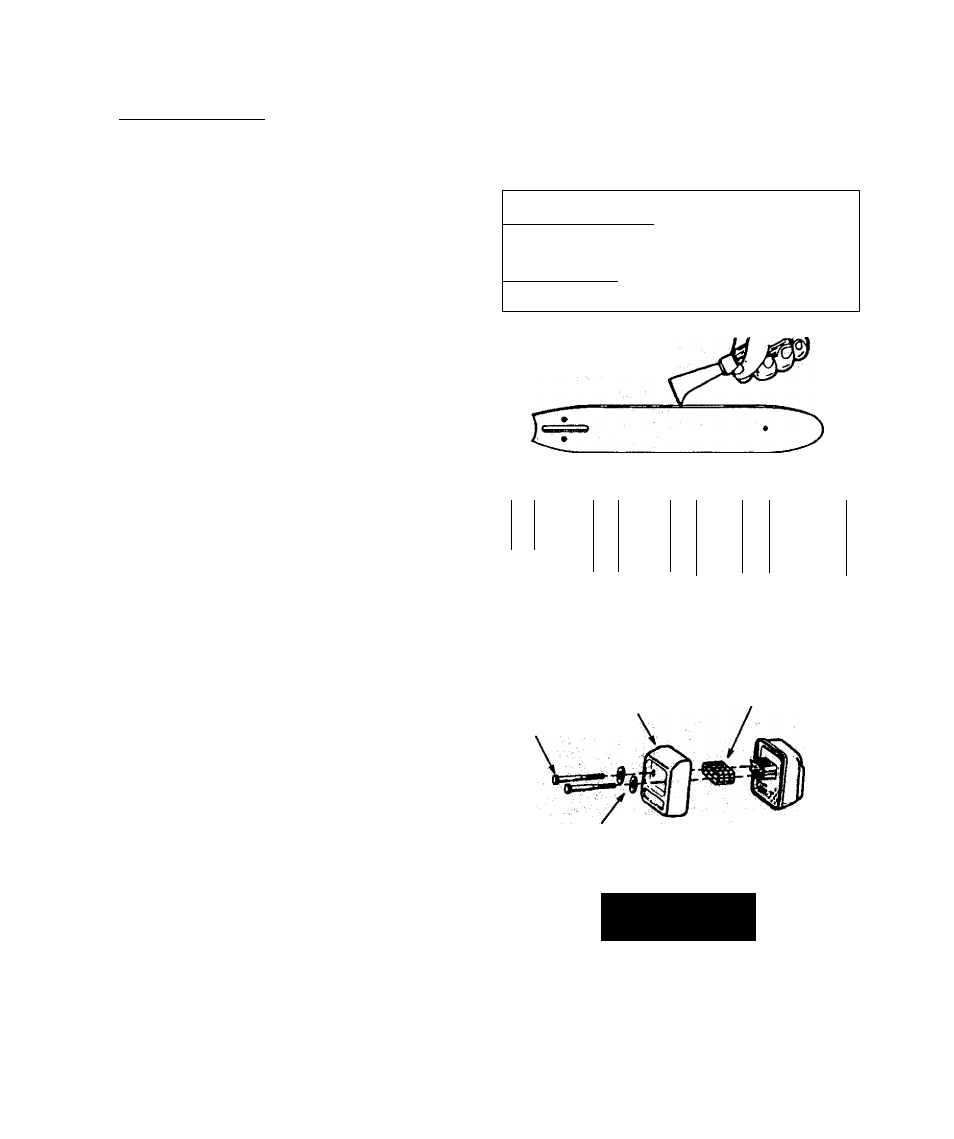
Items required: wire brush, 3/8” wrench
1, Disconnect the spark plug wire.
the muffler cover screws and washers.
Remove the muffler cover. Figure 36.
3 iftemove the spark arrestor screen. Figure 36.
4. Clean the screen with a wire brush or replace if
breaks are found.
5. Reassemble parts.
Muffler
Cover
Screws
Muffler
Cover
Spark Arrestor Screen
Washers
Figúrese
HtLAl)
SPECIAL SAFETY SECTION
FREQUKN’M.Y
- 1 7 -