B. single tine replacement warning, C. removing and replacing the tine holders, Warning – Troy-Bilt 12087 User Manual
Page 55
Attention! The text in this document has been recognized automatically. To view the original document, you can use the "Original mode".
B. Single Tine Replacement
WARNING
The tines or fine hood edges
may be sharp. Wear thick
gloves to protect your hands
from cuts or scrapes.
1. Move the Wheels/Tines/PTO
Drive Lever to NEUTRAL, the
Wheel Speed Lever to either FAST
or SLOW position, and the Tines/
PTO Clutch Lever to ENGAGE.
2. Gently tilt the tiller forward
until the engine rests on the ground.
C. Removing and Replacing
the Tine Holders
£k
WARNING
The tines or tine hood edges
may be sharp. Wear thick
gloves to protect your hands.
The 16 Bolo Tines are mounted
eight per side on left-side and
right-side tine holders - on either
Style A or Style B holders (refer to
Figures 5-33A and 5-33B to see
which style tine holder you have).
Style “A” tine holders are secured
to the tine shaft with two bolts and
two nuts. Style “B” tine holders
are secured with a single end bolt
to the left and right sides of the
tine shaft. Here’s how to replace
the tines and holders as assemblies.
Removal Steps:
1. Follow steps l-through-3 in
“Single Tine Replacement” above.
2. Identify the tine holders as
Style A or Style B, then as left-side
and right-side holders - they must
be replaced on the same side from
which they were removed. Use a
piece of chalk or a grease pencil to
mark them “L” and “R.”
3. With Style A holders, remove
the two bolts and nuts securing
each holder (Fig. 5-33A). With
Style B holders, remove the single
bolt (along with the washers) from
3. Raise the hood flap at the back
of the tiller and tie it up with string.
4. Before removing a tine, note in
which direction the bent tip points.
The new tine must be installed in
the same direction.
5. Use two 9/16" wrenches to re
move the two bolts and nuts secur
ing the tine to the tine holder plate
(see Photo 5-32). Use penetrating
oil on the hardware if it is rusted or
hard to remove.
6. Mount the new tine exactly the
way the old tine was positioned.
(The sharp edge of the tine, which
the very end of the tine shaft (Fig.
5-33B).
4. Use a soft mallet to
drive the holder off the
tine shaft. (Use a heavy
hammer and block of
wood to drive off a
“frozen” tine holder.)
5. When the holder is
off, clean all dirt and de
bris from the shaft and
the holder. Apply fresh
grease to the tine shaft.
Replacement Steps:
1. Replace the holder so
the sharp tine edges face
forward (toward front of
tiller). Tap tine holder
back on the tine shaft.
2. Grease the threads on
the mounting bolt(s).
Install and tighten the
bolt(s) securely.
WARNING
Wear
safety
goggles to pro
tect your eyes.
When loosening
hardware, do not
hit a wrench with
a
metal
tool-
this could shat
ter the tool or
wrench, sending
metal
particles
into your eyes.
55
Photo 5-32: Removing a single tine
requires taking off two bolts and
two nuts.
enters the soil first, must face for
ward when above the tine shaft.)
Replace the bolts and nuts and
tighten them securely.
Style A Tine Holder
Non-Tapered Tine Shaft
r'*- * ‘
^
Right-Side
Tine Holder
Left-Side
Tine Holder
Figure 5-33A: Style “A ” Tine Holders
—
Left and
right-side tine holders are secured to the tine
shaft with two bolts and two nuts.
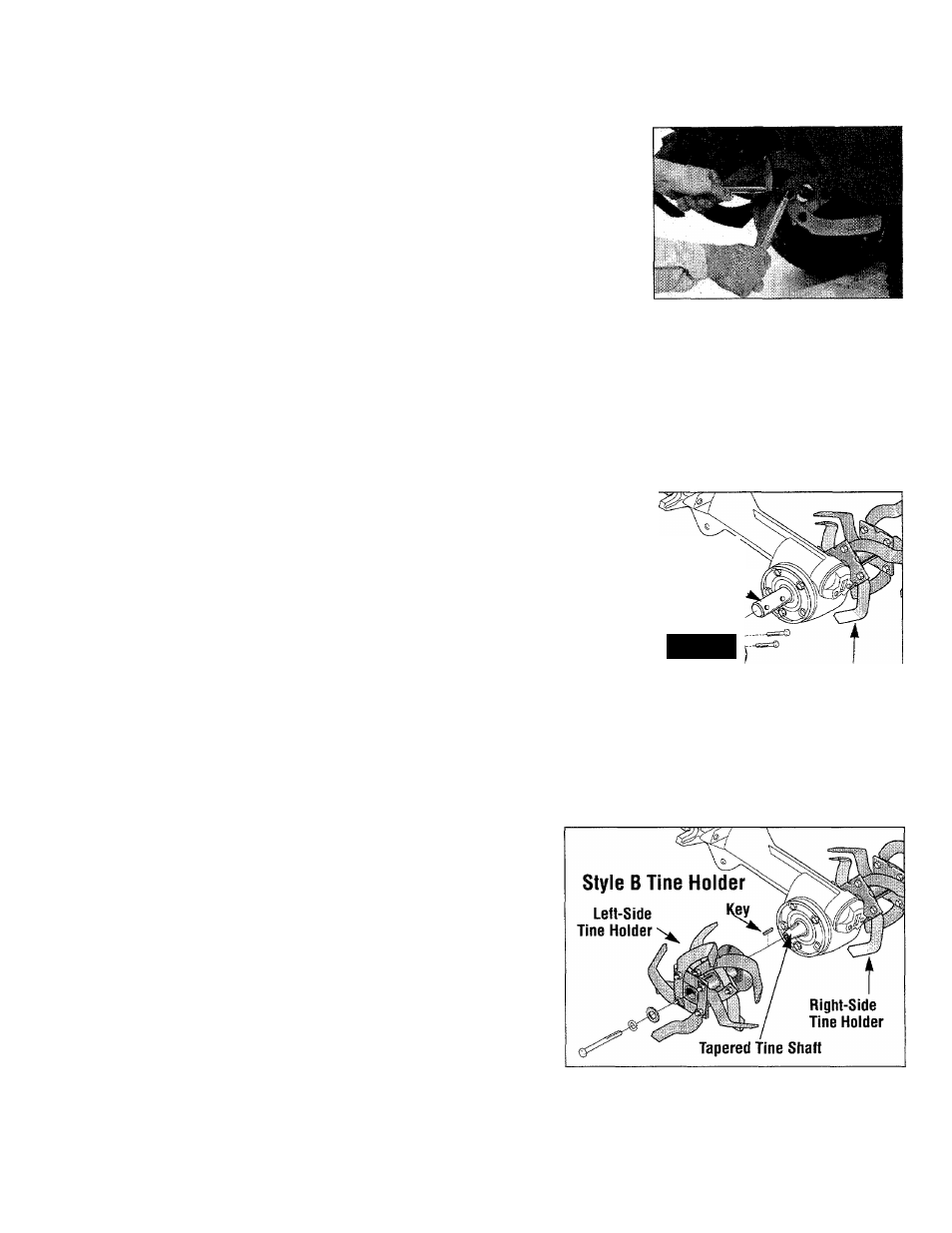
Figure 5-33B: Style “B” Tine Holders
—
Left and
right-side tine holders are each secured with a
single mounting bolt into the end of the tine