C. checking and adjusting the reverse drive system, Warning – Troy-Bilt 12087 User Manual
Page 53
Attention! The text in this document has been recognized automatically. To view the original document, you can use the "Original mode".
C. Checking and Adjusting the
Reverse Drive System
WARNING
To help avoid personal injury,
stop the engine, remove the
electric start key, disconnect
the spark plug wire and move
the wire away from the plug,
and let the engine and muf
fler cool down before inspect
ing or adjusting the reverse
drive parts.
When the Wheels/Tines/PTO
Drive Lever is moved up into RE
VERSE, the engine and engine
mount move down to press on the
reverse adjustment bolt (see Photo
5-24). This action compresses the
reverse spring and plunger assem
bly, requiring you to hold the lever
up in REVERSE. When you re
lease the lever, the spring automat
ically pushes the lever back into
NEUTRAL position.
number of reverse drive operating
problems, as explained next.
Check Action of Reverse Disc:
1. Verify that the linkages for the
Wheels/Tines/PTO Drive Lever are
lubricated with oil and the engine
mount bars and the belt adjustment
block are lubricated with grease.
(See “Tiller Lubrication” in this
section.)
2. Place the Wheels/Tines/PTO
Drive Lever in NEUTRAL.
Briefly pull out the engine recoil
start rope while watching the re
verse disc. The disc should turn,
but the lower pulley should not
(refer to Photo 5-25). If the re
verse disc turns the lower pulley, or
if it is located closer than 3/16" to
the pulley, the reverse adjustment
bolt should be adjusted upward
(see instructions that follow).
Moving the adjustment bolt up
ward will also solve the problem of
a tiller that goes into REVERSE on
its own.
3. Use your left hand to hold the
Wheels/Tines/PTO Drive Lever up
in REVERSE, while briefly
pulling out the engine start rope.
The reverse disc should turn the
lower pulley (see Photo 5-26). If
not, or it requires a lot of pressure
to hold the lever up in REVERSE,
then the reverse adjustment bolt
must be adjusted downward.
When correctly adjusted, the
Wheels/Tines/PTO Drive Lever
should “pop” out of reverse when
the lever is released, but not re
quire exceptional effort to hold it
up in the reverse position.
4. Shift the Wheels/Tines/PTO
Drive Lever to REVERSE and then
let it go. The lever should return to
NEUTRAL. If not, the reverse ad
justment bolt will have to be ad
justed upward.
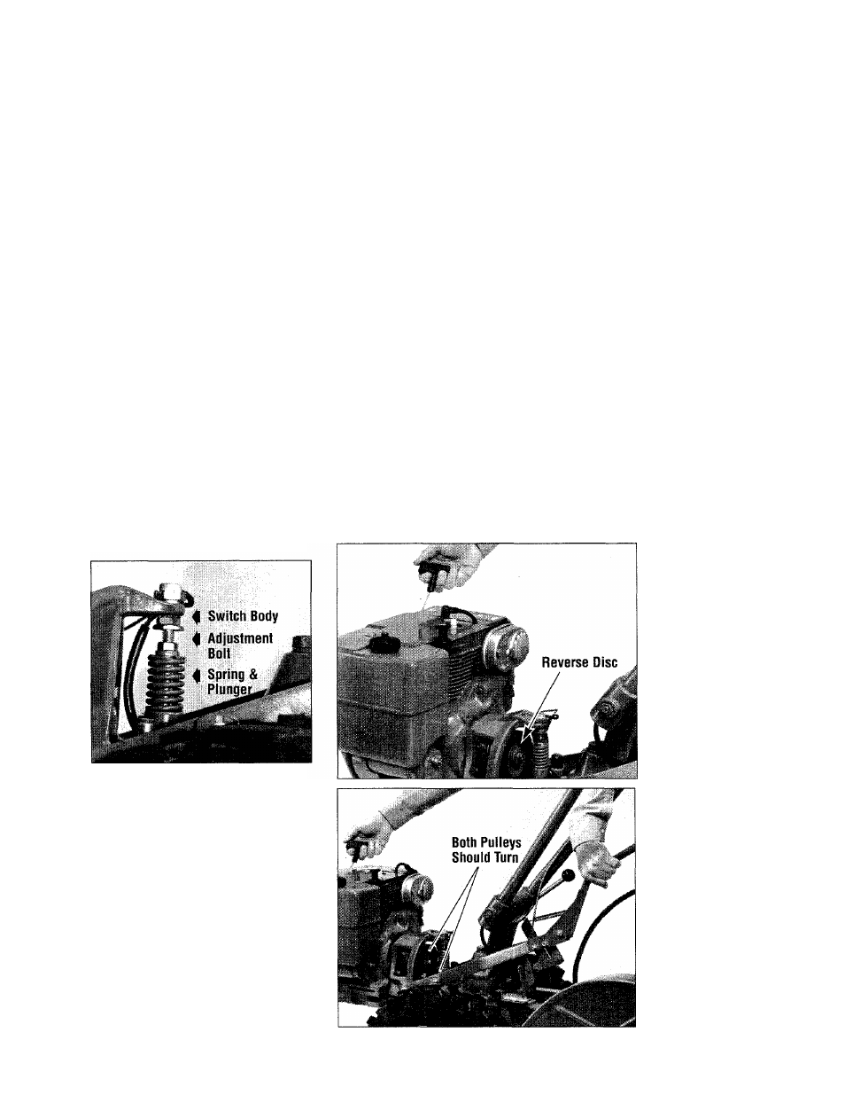
Photo 5-24: Spring and plunger as
sembly.
The spring and plunger assem
bly is designed to prevent the re
verse disc from making contact
with the transmission pulley until
you shift into REVERSE. When
the lever is in NEUTRAL, the
switch body on the bottom of the
engine mount tab should be resting
squarely on top of the reverse ad
justment bolt (Photo 5-24). The
reverse adjustment bolt can be ad
justed up or down to correct a
Photo 5-25: With
shift lever in NEU
TRAL, only the re
verse disc should
turn when starter
rope is pulled out.
Photo 5-26: With
shift lever in RE
VERSE, the reverse
disc should turn
the transmission
pulley when the
starter rope is
pulled out.
53