Tines/pto clutch lever, Depth regulator lever, Warning – Troy-Bilt 12087 User Manual
Page 22: Handlebar height adjustment lever, Engine features and controls identification
Attention! The text in this document has been recognized automatically. To view the original document, you can use the "Original mode".
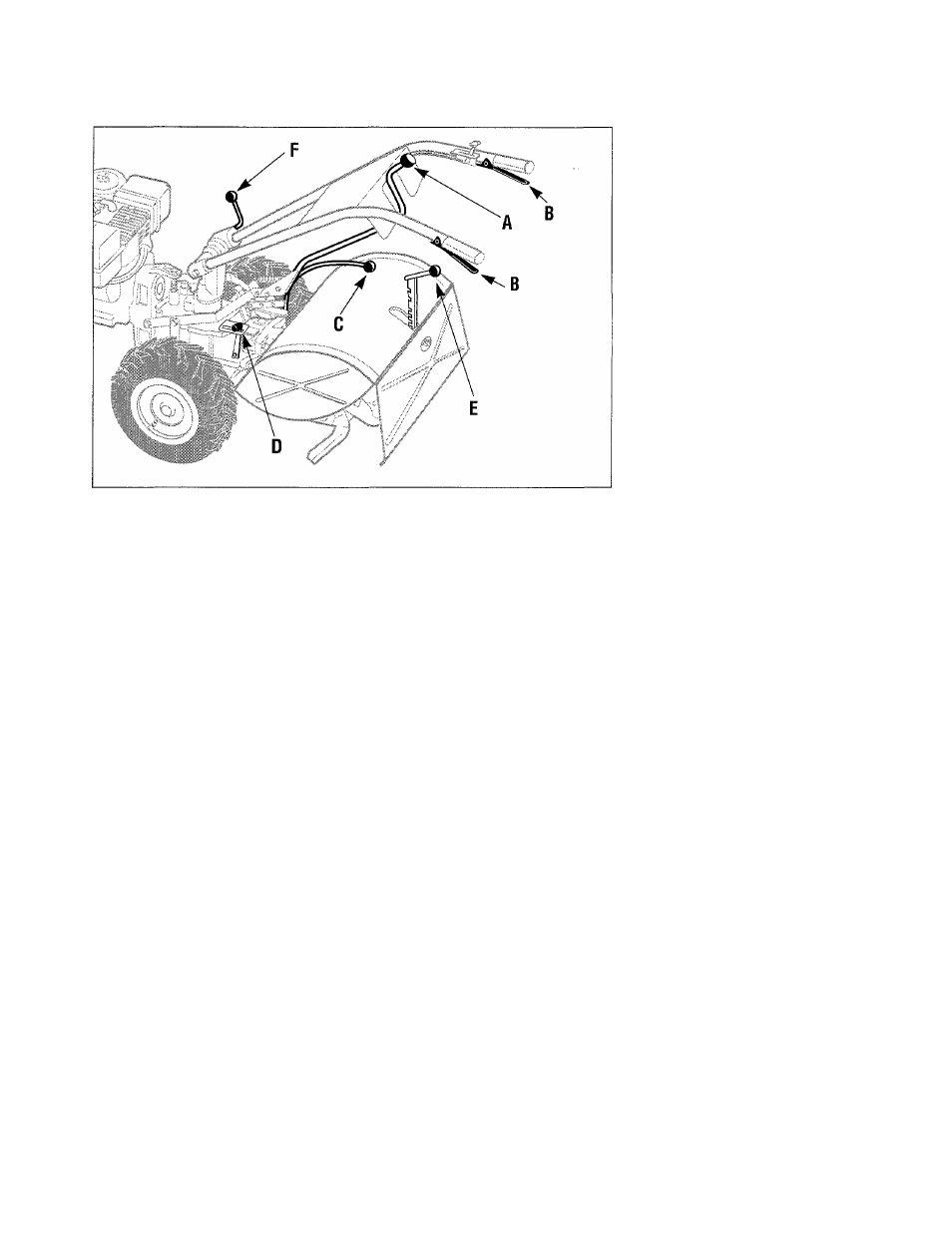
Figure 3-2: A- Wheels/Tines/PTO Drive Lever; B- Forward Interiock
Levers; C- Wheel Speed Lever; D- Tines/PTO Clutch Lever; E- Depth
Regulator Lever; F- Handlebar Height Adjustment Lever.
Tines/PTO Clutch Lever
Use this lever (D, Figure 3-2) to
engage or disengage power from
the transmission PTO clutch to the
tines or any PTO attachment. It has
two operating positions: ENGAGE
and DISENGAGE.
ENGAGE - Lever moved into de
tent slot furthest from engine. Use
to operate tines or other PTO attach
ments. After shifting to ENGAGE,
briefly operate machine in
FORWARD to help fully engage the
PTO clutch.
DISENGAGE - Lever moved into
detent slot nearest engine. Use to
disengage power to tines or other
PTO attachments before transport
ing, loading, turning, or backing up.
• To avoid transmission damage,
always put the Wheels/Tines/
PTO Drive Lever in NEUTRAL
before shifting the Tines/PTO
Clutch Lever.
Depth Regulator Lever
Use this lever (E, Figure 3-2) to
regulate the tilling depth of the
tines. It also has a TRAVEL posi
tion, which places the tines out of
the ground.
To operate the lever, pull it
straight back and then slide it up or
down to any of the eight notched
settings.
The highest notch is the
TRAVEL setting. For shallow till
ing and cultivating, use the second
or third notch from the top. The
other notches are for deeper tilling
and for power composting.
WARNING
To avoid personal injury,
always place the tines in the
TRAVEL position before start
ing the engine. This prevents
the tines from touching the
ground until you are ready to
begin tilling.
Handlebar Height
Adjustment Lever
Use this lever (F, Figure 3-2) to
adjust the handlebars at one of the
two preset height settings.
To change the height, hold the
handlebars with one hand and
loosen the lever in a counterclock
wise direction. Move the handle
bars to one of the two preset height
settings and retighten the lever.
• Swapping the positions of the in
side handlebar ratchets (see Page
11) will change the preset set
tings by a few inches.
WARNING
For use with the PTO Chipper/
Shredder
attachment
only,
the handlebars can be swung
30° to tbe right side by loos
ening the mounting bolt at
the bottom of the handlebar
base. Never operate your
tiller or other attachments
with the handlebars swung
out to the right side. This
could result in unsafe han
dling and personal injury.
ENGINE FEATURES AND
CONTROLS IDENTIFICATION
The following are descriptions
of the controls on your engine.
Additional engine information is
provided in Section 4 “Operation”
and in the engine manufacturer’s
Owner’s Manual which was in
cluded in your literature package.
Be sure to read the engine Owner’s
Manual carefully and save it for fu
ture reference.
WARNING
To avoid serious personal in
jury or damage to equipment,
do not start your engine at
this time. Complete starting
instructions are described in
Section 4 “Operation.”
22