Danger, Step 2: connect the wire harness receptacle – Troy-Bilt 12087 User Manual
Page 18
Attention! The text in this document has been recognized automatically. To view the original document, you can use the "Original mode".
Second Alternative Charging Mdhod:
Charge the battery at a rate from
6-to-12 amperes until all cells gas
freely. Do not exceed 4 hours
charging time.
B. Turn off the charging equip
ment and disconnect the charger
cables from the battery terminals.
C. Recheck electrolyte level in
each cell. Top off any low cells
with electrolyte solution up to the
“Upper” level line.
D. Securely replace all six filler
caps. Use a baking soda and water
mixture to rinse off electrolyte that
may have spilled on the battery.
A DANGER
Never jump start the battery
with a vehicle battery or charg
ing system. This may produce
a battery explosion, causing
acid or electrical burns.
DANGER
To Avoid Personal Injury or
Property Damage;
• Batteries produce explosive
gases - always keep sparks
and flame away from battery.
• Ventilate area when charg
ing or using the battery.
•
During charging, don’t
leave
battery
unattended.
Charging time need not be
continuous.
• Follow safety rules and in
structions supplied by battery
and charger manufacturers.
• Do not charge battery at a
rate higher than 12 amperes
to avoid generating excessive
heat and gassing which could
damage the battery.
DANGER
To Avoid Personal Injury or
Property Damage:
• Do not touch positive bat
tery terminal and any sur
rounding metal objects with
tools, jewelry or other metal
items.
Failure
to
comply
could cause a short circuit
leading to electrical burns or
explosion of battery gases.
• Never bring a gas can near
the positive (+) battery termi
nal. A short circuit could
occur leading to an explosion
of the gasoline or the battery
gases. Always fill the engine
fuel tank from the front or
side of the engine.
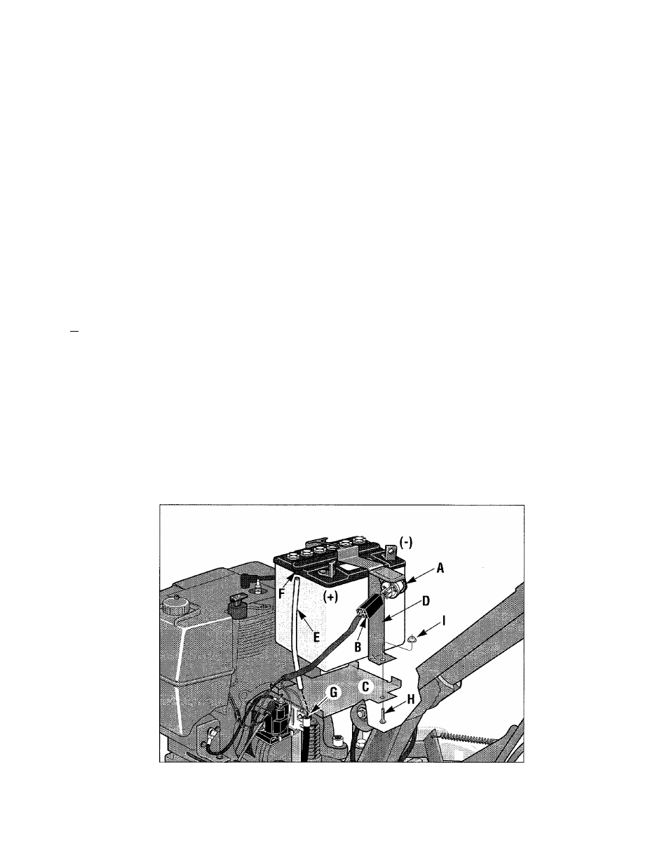
STEP 2: Connect the Wire
Harness Receptacle
A. The keyswitch (A, Figure 2-25)
is part of the hold-down clamp as
sembly (D). The prongs at the
back of the keyswitch must be se
curely inserted into the plastic wire
harness receptacle (B).
B. Remove the pair of ignition
keys from the keyswitch. Store
them safely away. Do not put a
key in the keyswitch until you have
read the sections in this
Owner/Operator Manual covering
features, controls and operation.
Figure 2-25: First connect Keyswitch (A) to wire harness (B). Then, the acti
vated battery must be secured to mounting platform (C) using the hold
down clamp (D) with its mounting hardware (H, I). Last, install plastic vent
tube (E) over the vent fitting (F), and down into vent tube shield (G).
18