Drive clutch – MTD 406 User Manual
Page 11
Attention! The text in this document has been recognized automatically. To view the original document, you can use the "Original mode".
V,
DEPTH STAKE ADJUSTMENT
To adjust the depth stake, refer to “How To Use Your
Tiller” on pages 9 and 10.
BELT TENSION ADJUSTMENT
Tine Clutch
Periodic adjustment of the belt tension may be
required due to normal stretch and wear on the belt.
Adjustment is needed if the tines seem to hesitate
while tilling, but the engine maintains the same speed.
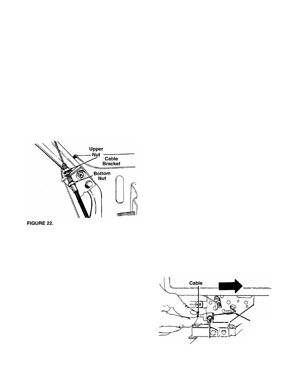
To adjust, loosen the hex nuts at the cable bracket on
the handle. See figure 22. With the clutch lever
released as shown in figure 16, adjust the bottom nut
so that there is only a slight amount of slack in the
control wire. Tighten the upper nut against the brack
et.
NOTE:
Do not overtighten control wire. Too much ten
sion may cause it to break.
Drive Clutch
if adjustment is needed, refer to final adjustment sec
tion of Assembly instructions.
If through normal operation the belts become
stretched or worn, and there is no adjustment left at
the cable brackets on the handles and handle panel,
the other end of the cables may be adjusted as fol
lows.
a. If the tiller does not have forward motion with the
forward drive clutch lever engaged, adjust the for
ward drive cable by loosening the hex nut in back
of the cable bracket on the tiller a few turns, then
tightening the hex nut in front of the bracket. Refer
to figure 9.
b. If the tiller does not have reverse motion with the
reverse drive clutch lever in reverse, adjust the
reverse cable by loosening the hex nut in front of
the cable bracket on the tiller a few turns, then
tightening the hex nut in back of the bracket. When
correctly adjusted, the reverse idler should be
toward the middle of the slot as shown in figure 15.
When making either of the above adjustments (a or
b), be certain to recheck the neutral adjustments on
the tiller (steps A and B in first column on page 8).
CARBURETOR ADJUSTMENT
A
WARNING: If any adjustments are made
to the engine while the engine is running,
(e.g. carburetor), disengage all clutches
and tines. Keep ciear of ali moving parts.
Be careful of heated surfaces and muf
fler.
Minor carburetor adjustment may be required to com
pensate for differences in fuel, temperature, altitude
or load. If adjustments are needed, refer to the engine
manual packed with the tiller.
NOTE:
A dirty air cleaner will cause engine to run
rough. Be certain air cleaner is clean and attached to
the
carburetor
before
adjusting
carburetor.
Do
not
make
unnecessary
adjustments.
Factory
settings
are
satisfactory for most applications and conditions.
THROTTLE CONTROL ADJUSTMENT
To obtain satisfactory engine performance, the engine
throttle control must be adjusted properly. If it is nec
essary to check the engine control adjustments, pro
ceed as follows.
1. Loosen the cable clamp screw. See figure 23.
2. With the throttle control in FAST position and the
cable connected to the adapter lever, push the
cable through the cable clamp in the direction
shown in figure 23 until the adapter lever is as far
up as it will go.
3. Tighten the cable clamp screw.
4. Check that the engine stops when throttle control
is moved to STOP position. If engine does not
stop, loosen the cable clamp screw and readjust
by pulling cable backward slightly until engine
stops. Retighten cable clamp screw.
Adapter
Lever
Cable Clamp
Screw
FIGURE 23.
11