Electrical connections, Electrical junaion box, Wiring – Generac Power Systems 00862-1 User Manual
Page 26: Generator ac connections, Conduit, Generator ac connection system, Electrical junction box, Conduit -25
Attention! The text in this document has been recognized automatically. To view the original document, you can use the "Original mode".
ELECTRICAL CONNECTIONS
Be sure to read “Generator AC Connection System”
on Page 14.
The following general rules apply to electrical connec
tions in a recreational vehicle:
• Qualified electricians who are familiar with applicable codes,
standards and regulations should install electrical wiring.
• The wiring should comply with codes, standards and reg
ulations. The National Electric Code (NFPA 70), as well
as state and local codes, apply.
• Switches and circuit breakers should be of a type approved
for use in recreational vehicles and must be mounted and
installed to prevent damage from road shock.
• Wiring must be of adequate size, with approved insulative
qualities, and properly supported.
• Conduit and wire openings into generator compartment
(if used) must be vapor-sealed, to prevent entry of flam
mable, explosive or poisonous gases into the vehicle.
ELECTRICAL JUNaiON BOX
Install an approved, square electrical junction box that
has a blank cover on the interior or exterior wall of the
area you plan to install the generator (NOT on the
generator). Route the generator's AC output leads
into this junction box through approved flexible con
duit, and into this junction box. This is the point of first
termination for generator AC output leads.
WIRING
• Wiring should be of stranded copper to reduce chance
that vibration may cause breakage.
• Wire gauge size should be large enough to handle at
least 115% of the installed generator's rated maximum
current.
• If neutral conductors are used, they must be the same
size as other leg wires.
• Route power supply conductors from generator AC output
leads T1 (red), T2 (white), T3 (black) and the green
ground wire through approved flexible conduit to the elec
trical junction box on the compartment wall.
If flexible metal conduit is used between the generator
and the compartment junction box, the conduit end that
terminates the compartment junction box, must be vapor-
sealed. Flexible metal conduit is NOT vapor tight along its
entire length.
• From the junction box route power supply wires through
approved conduit to either (a) double-pole, double-throw
transfer switch, or (b) approved isolation receptacle.
Connecting to a transfer switch or isolation receptacle
must prevent vehicle electrical circuits from being con
nected to two different power supplies at the same time
(such as generator and dockside power).
• Conductors must be rated 221°F (105°C) or must be of a
larger conductor size.
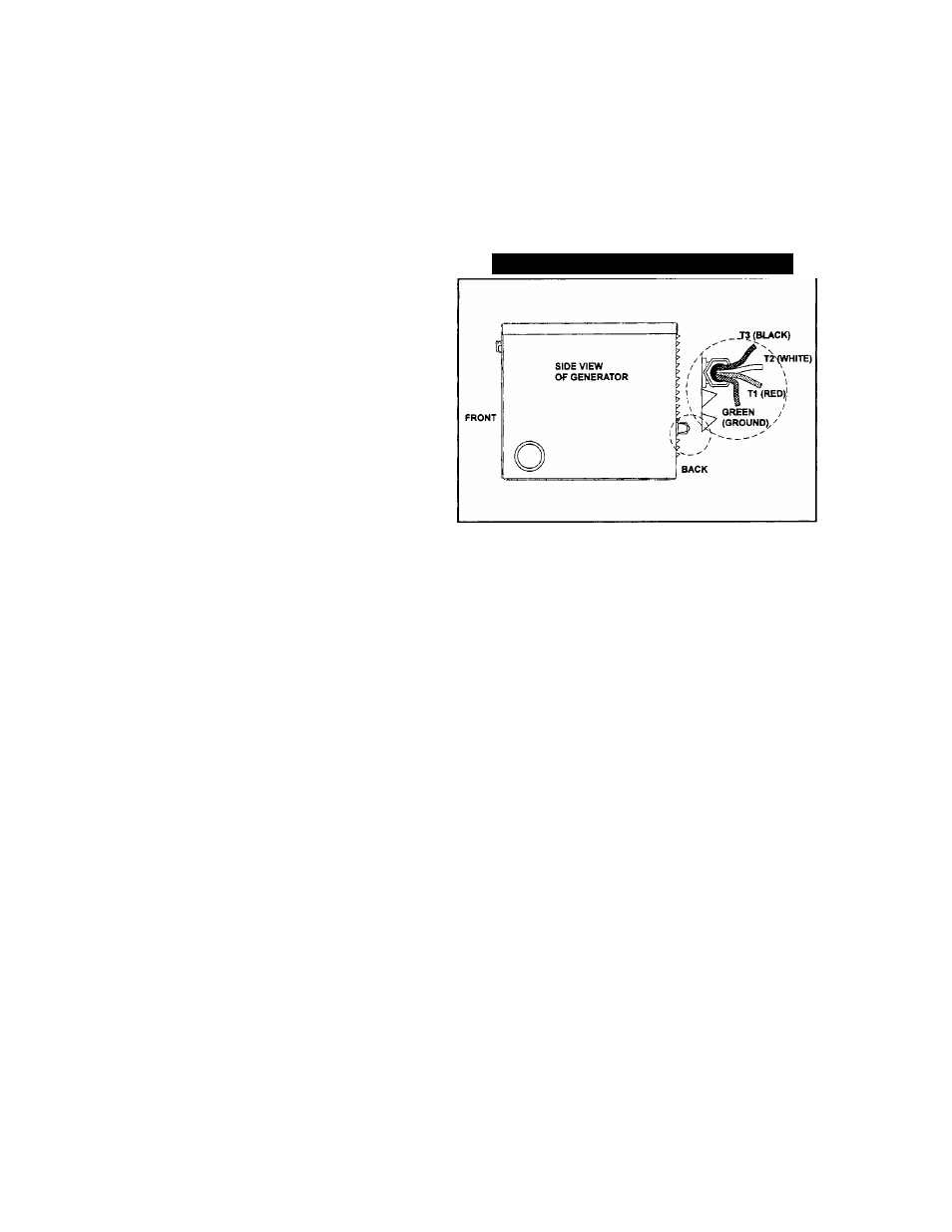
GENERATOR AC CONNECTIONS
Generator AC output leads T1 (red), T2 (white), T3
(black) come out of the generator as shown in Figure
29. Lead T1 (red) and T3 (black) are “hot” while T2
(white) is the grounded “neutral” lead. There is also a
green lead that connects to ground in the junction box
of the recreational vehicle.
Figure 29 — Generator AC Output Leads
Line T1 (red) to T2 (white) is protected against over
load by a 30 amp circuit breaker (CB1). Use this line
-to-neutral connection separately to operate 120 volts,
single phase, 60 Hz, AC loads requiring up to 3600
watts (3.6 kW) of power. Line T3 (black) to T2 (white)
is also protected against overload by a 20 amp circuit
breaker (CB2). Use this line-to-neutral connection
separately to operate similar loads. However, be sure
the total unit load does NOT exceed the maximum
rating of the generator. The neutral line (T2,white) on
all units is a grounded neutral.
A
CAUTION: Do NOT connect electrical loads in
excess of any circuit breaker rating or you will
develop problems with circuit breaker tripping,
which causes a loss of AC output. Also, do NOT
exceed the generator's rated wattage capacity. Add
the watts or amperes of all lighting, appliance, tool
and motor loads the generator will operate at one
time. This total should be less than the unit's rated
wattage/amperage capacity.
CONDUIT
Route the connections between the generator and the
junction box through approved, flexible conduit. The
following general rules apply:
• Cut wiring to the required length and allow extra wire for
junction box connections.
• Carefully prepare conduit ends, to prevent sharp edges
from cutting through wiring insulation.
• Route conduit so it does not interfere with generator
movement.
24-