Purpose and scope of manual, Safety, Standards booklets – Generac Power Systems 00862-1 User Manual
Page 16: Equipment description, Engine generator operating speed, Generator ac connection system, General installation information
Attention! The text in this document has been recognized automatically. To view the original document, you can use the "Original mode".
GENERAL INSTALLATION INFORMATION
PURPOSE AND SCOPE OF MANUAL
These
Installation
Instructions
have
been
prepared
especially for the purpose of familiarizing installers
and owners of the applicable equipment with the pro
duct's installation requirements. Give serious consid
eration to all information and instructions in the manu
al, both for safety and for continued reliable operation
of the equipment.
Because of the different recreational vehicle models
and the variations between the models, it would be
extremely
difficult,
if
not
impractical,
to
provide
detailed instructions on every installation possibility.
For that reason, instructions and illustrations in this
manual are general in nature. Illustrations are not
intended to serve as detailed installation blueprints.
The installation should comply strictly with all applica
ble codes, standards and regulations pertaining to the
installation and use of this product. If any portion of
this manual appears to be in conflict with such codes,
standards or regulations, the applicable codes, stan
dards,or regulations must take precedence over the
manual.
SAFETY
Before handling, installing, operating or servicing this
equipment, be sure to read carefully the “Notice to
Installer” and “Safety Rules” at front of this manual.
Comply with all SAFETY RULES to prevent death,
personal injury or damage to equipment and/or prop
erty. Stress safety to all installers, operators and ser
vice technicians who work on this equipment.
STANDARDS BOOKLETS
Installation,
use
and
servicing
of
this
equipment
should comply strictly with published standards, as
well as the manufacturer's recommendations. The fol
lowing standards booklets (latest revision) are avail
able from the sources indicated:
1.
NFPA Standard 501C, “Standard for Recreational
Vehicles”, available from the National Fire Protection
Association, Batterymarch Park, Quincy, MA 02269.
2. NFPA 70, “NFPA Handbook of the National Electric
Code”, obtained from same address as Item 1.
3. ANSI Cl-1975 and ANSI 119.2-1975, available from the
American National Standards Institute, 1430 Broadway,
New York, NY 10018.
4.
ANSI
A119.2/NFPA
501C,
available
from
the
Recreational Vehicle Association, 1896 Preston White
Drive, Reston, VA 22090.
5. California Administrative Code, Title 25, available from
the State of California, Documents Section, P.O. Box
1015, North Highlands, CA 95660.
6. CSA Electrical Bulletin 946, available from the Canadian
Standards
Association,
Housing
and
Constructions
Materials Section, 178 Rexdale Boulevard, Rexdale,
Ontario, Canada, M9W 1R3.
EQUIPMENT DESCRIPTION
Instructions and information in this section pertain to
Generac air-cooled generators. These generators are
designed specifically for installing in recreational vehi
cles. They operate 120 volt, single phase, 60 Hertz, AC
electrical loads that require 46.0 amps at 120 volts.
ENGINE GENERATOR
OPERATING SPEED
The generator’s revolving field (rotor) is driven by a
single-cylinder, 4-cycle engine through a pulley and
drive belt arrangement. The generator supplies 120
volts AC at 60 Hertz when the rotor is operating at
3600
rpm.The
drive
belt
arrangement
allows
the
engine to operate at a lower speed than the rotor.
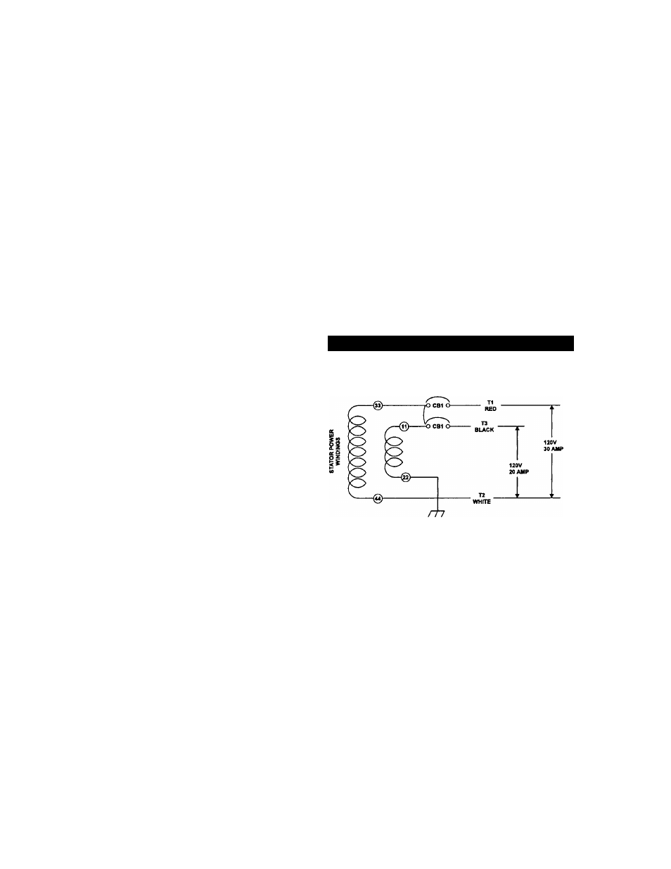
GENERATOR AC CONNECTION
SYSTEM
The generator is equipped with dual stator power
windings as shown in figure 13.
Figure 13 — 120 Volt Single Voltage Connection
OROUNDED
NEUTRAL
• The AC connection system on all air-cooled QP series
generators uses a GROUNDED neutral.
• A separate green ground wire is connected to the recre
ational vehicle’s junction box.
• For these QP55 units, loads connected across T1 (red) to
T2 (white), MUST NOT exceed 30 amperes or 3600 watts
and loads connected across T3 (black) and T2 (white)
MUST NOT exceed 20 amperes or 2400 watts each at
120 volts. The combined loading of the two breakers
should not exceed 5500 watts.
IMPORTANT: DO NOT CONNECT LOADS IN EXCESS OF
CIRCUIT BREAKER RATINGS.
— 1 4 —