Depth bar installation, Tine assemblies – MTD 219-320-000 User Manual
Page 8
Attention! The text in this document has been recognized automatically. To view the original document, you can use the "Original mode".
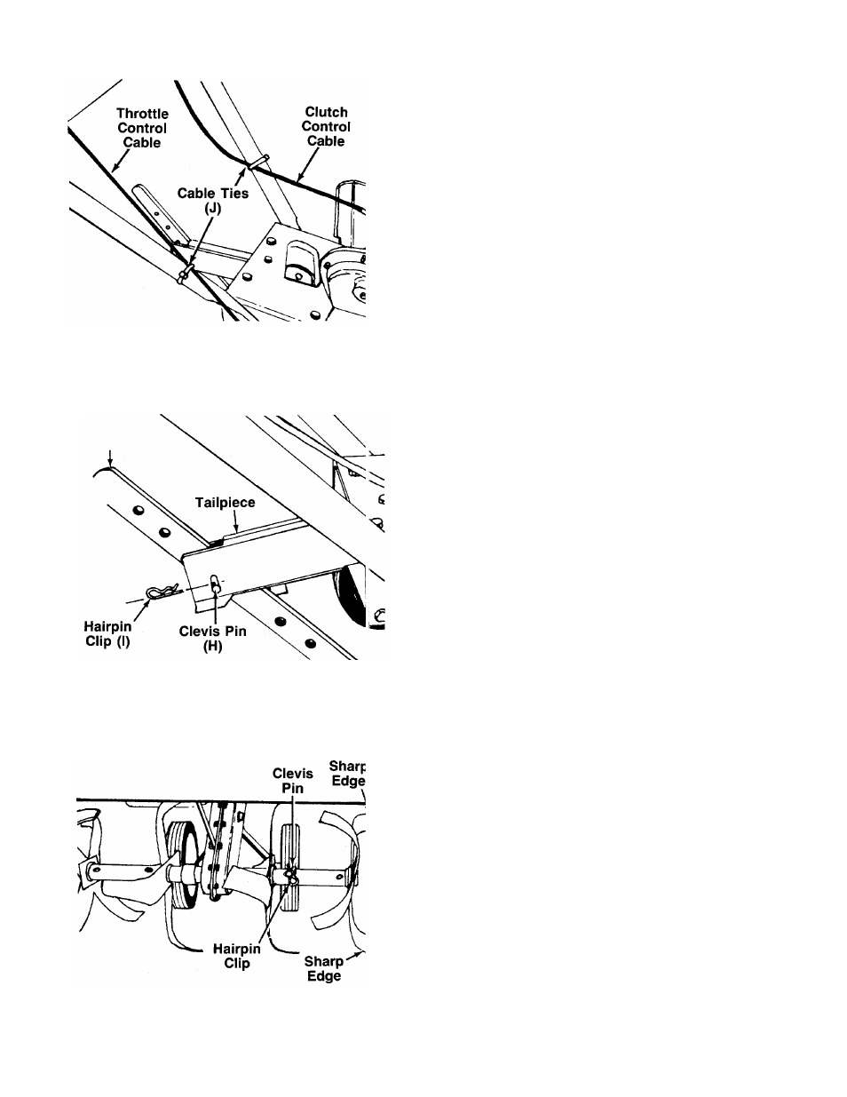
6. Secure the throttle control cable and clutch con
trol cable to the handles with cable ties (J) provid-
—ed. Cut off excess ends. See figure 13.
FIGURE 13.
DEPTH BAR INSTALLATION
Place the depth bar in position on the tailpiece. Secure
with clevis pin (H) and hairpin clip (I). Round end of
-depth bar goes to the top. See figure 14.
FIGURE 14.
TINE ASSEMBLIES
Check to be certaint the tine assemblies are on the tine
shaft so that the sharp edge enters the soil first. See
-figure 15.
3
FIGURE 15.
See also other documents in the category MTD Gardening equipment:
- 113-890-033 (8 pages)
- 246-685-000 (16 pages)
- 110-420R000 (19 pages)
- 112-516R000 (16 pages)
- 111-902-026 (14 pages)
- 112-530 (10 pages)
- CC4025 (88 pages)
- 112-120-120 (12 pages)
- 215-035-000 (16 pages)
- Y26SS (56 pages)
- Y780 (56 pages)
- 24665-9 (12 pages)
- CC4125 / CC4175 (48 pages)
- 114-062-000 (19 pages)
- 218-405-000 (23 pages)
- 110-902-033 (4 pages)
- 219-406-000 (24 pages)
- 241687 (12 pages)
- 219-381-000 (24 pages)
- 112-011-300 (12 pages)
- TMO-33603B (16 pages)
- 675 thru 689 (12 pages)
- 110-122A (14 pages)
- 16K (44 pages)
- CC4105 (56 pages)
- 112-892-033 (7 pages)
- 243-675A (16 pages)
- 197-468A (6 pages)
- 24687-8 (16 pages)
- 110-300 (4 pages)
- 114-040A (8 pages)
- E660G (28 pages)
- 240677 (18 pages)
- Y700 (64 pages)
- 242-660-000 (8 pages)
- 11-094R000 (16 pages)
- 110-516R000 (20 pages)
- 25P (50 pages)
- 113-030A000 thru 113032D000 (16 pages)
- Y725 (68 pages)
- Y765 (64 pages)
- 244-600A (7 pages)
- YARD MACHINES 599 (54 pages)
- 24687L (16 pages)
- 10710-0 (11 pages)