Figure 15, To start engine, To stop engine – MTD 110-329A User Manual
Page 9: Important, Adjustments, Cutting height, Figure 16, Throttle
Attention! The text in this document has been recognized automatically. To view the original document, you can use the "Original mode".
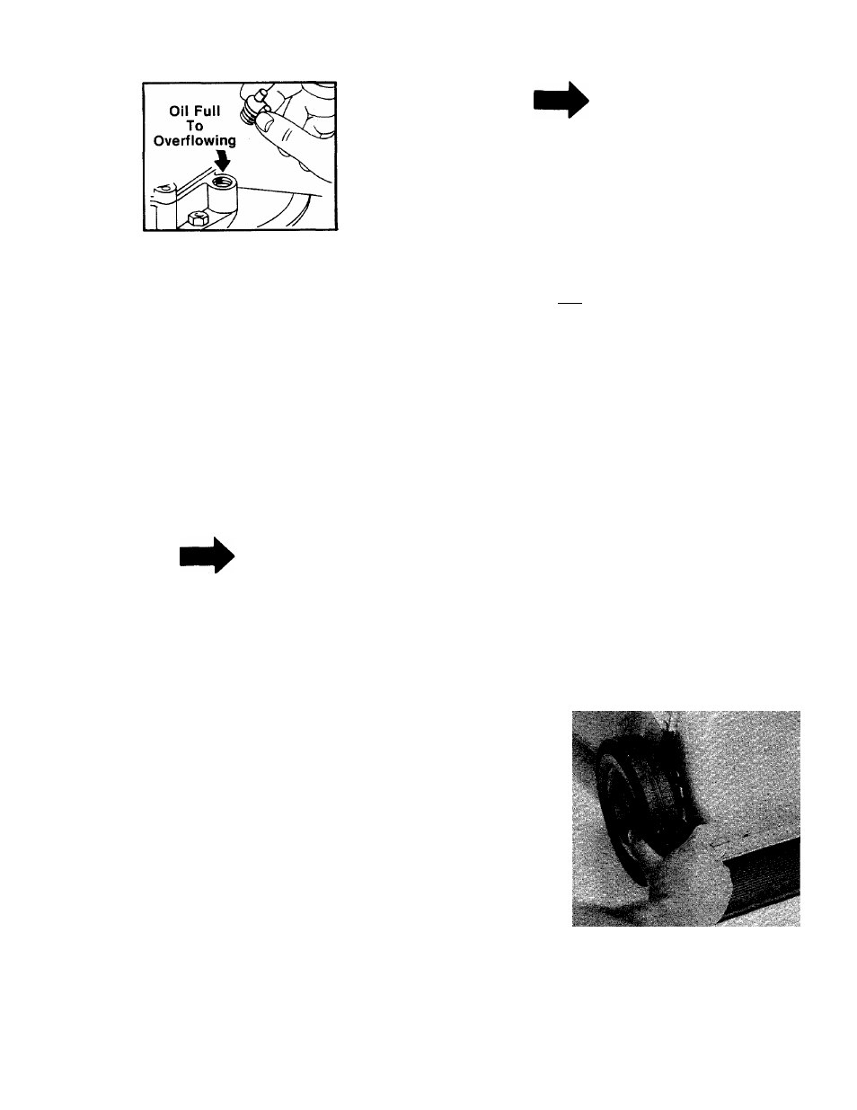
FIGURE 15.
3. Fill fuel tank, using clean, fresh, lead-free or
leaded “regular” grade automotive gasoline.
Fill tank completely.
DO NOT MIX OIL WITH GASOLINE.
TO START ENGINE
1. Move throttle control lever to “START” posi
tion.
2. Place foot on right side of deck and hold han
dle to prevent tipping the unit. Grasp starter
and pull out rapidly. Return it slo\wly to the
engine. Repeat if necessary.
NOTE
This engine features a unique
Automatic
Choke.
In
case
of
flooding, move control to “STOP”
and pull starter six times. Then
move control to “START” position
and start engine. If engine con
tinues to flood, rotate the carburetor
needle valve 1/8 turn clock\A/ise to
obtain a leaner mixture. See Car
buretor Adjustment on page 10.
This mower is designed to be operated at full
throttle to give you the best cut and do the most
effective job of bagging the cut grass.
TO STOP ENGINE
1. Move throttle control lever to “STOP” posi
tion.
2. Remove spark plug wire from spark plug and
ground to prevent accidental starting while
equipment is unattended.
Be sure that lawn is clear of stones, sticks, wire,
or other objects which could damage lawn mower
or engine. For best results and to insure more
even grass distribution, do not mow when lawn is
excessively wet.
IMPORTANT
After striking a foreign object, stop
the engine. Remove wire from spark
plug, thoroughly inspect the mower
for any damage, and repair the
damage
before
restarting
and
operating the mower.
ADJUSTMENTS
, , ^CAUTION
Do not at any time make any adjust
ment to lawn mower without first
stopping engine and disconnecting
spark plug wire.
CUTTING HEIGHT
An adjusting plate and thumb lever at each wheel
position provides cutting height adjustment. Each
adjusting plate has five holes. Height of cut will
be changed when the thumb lever is moved from
one hole to another. Simply depress the lever
towards wheel and move wheel and lever
assembly to desired position. See figure 16.
Cutting height will be raised as front and rear
levers are lowered. Cutting height will be lowered
as front and rear levers are raised. All wheels must
be positioned at the same height.
For rough or uneven lawns, move the wheels to a
position which will give a higher cutting height.
i-
FIGURE 16.
THROTTLE
If adjustment becomes necessary, the throttle
control wire assembly can be reset as follows: