Figure 17, Handle position, Warning – MTD 110-329A User Manual
Page 10: Carburetor adjustments (see figure 19)
Attention! The text in this document has been recognized automatically. To view the original document, you can use the "Original mode".
1.
2
.
3.
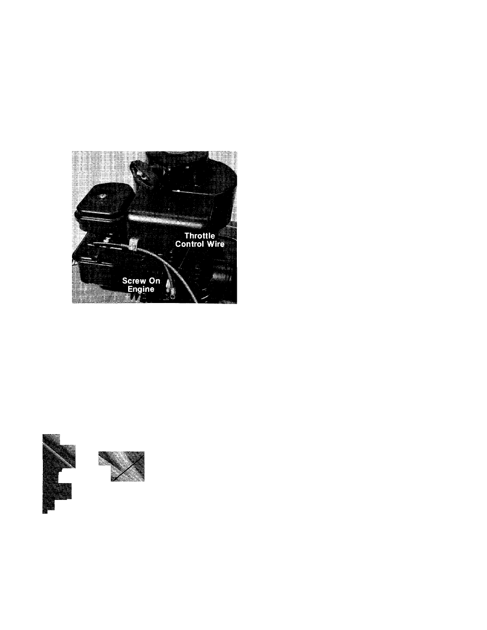
Loosen, but do not remove, the screw secur
ing throttle control wire assembly at engine.
See figure 17.
Move throttle control lever on handle to
“FAST” position.
Move lever to which control wire is fastened
at engine to full open position. Retighten
screw
to
secure
throttle
control
wire
assembly.
FIGURE 17.
HANDLE POSITION
The upper handle can be adjusted to a high or low
position. The operator of the lawn mower can easi
ly adjust the handle position by unscrewing the
two knobs, removing the two bolts and reassem
bling in the other position. No tools are necessary
to make this adjustment. See figure 18.
ir ^
' V
' I
■
t
- ► ■ 'll
WARNING
t
If any adjustments are made to the
engine while the engine is running
(e.g.
carburetor),
disengage
ail
clutches and blades. Keep clear of
all moving parts. Be careful of
heated surfaces and muffler.
FIGURE 18.
CARBURETOR ADJUSTMENTS (See figure 19)
Minor carburetor adjustments may be required to
compensate for differences in fuel, temperature,
altitude and load.
All carburetor adjustments should be made with
the air cleaner on engine. Air cleaner mounting
screw must be in carburetor when engine is run.
Best adjustment is made with a fuel tank half full
of gasoline.
To Adjust Carburetor:
1. Start engine and run long enough to warm it to
operating temperature.
If engine is out of adjustment so that it will
not start, close the needle valve by turning it
clockwise. Then open needle valve 1-1/2 turns
counterclockwise.
2. Move engine control to run engine at normal
operating speed.
a. Turn needle valve in clockwise until
engine starts to lose speed (lean mixture).
b. Then slowly turn needle valve out counter
clockwise past the point of smoothest
operation until engine just begins to run
unevenly (rich mixture).
c. Turn needle valve back in clockwise very
slowly till engine runs evenly.
d. Final adjustment of the needle valve
should be slightly to the rich side (turn
counterclockwise) of the mid-point.
3. Move engine control to SLOW. Turn idle ad
justing screw until a fast idle is obtained (1750
R.P.M.).
4. To check adjustment, move engine control
from SLOW to FAST speed. Engine should ac
celerate smoothly. If engine tends to stall or
die out, increase idle speed or re-adjust car
buretor, usually to a slightly richer mixture.
10