Assembly, Install seat (see fig. 3), Check tire г – Poulan 165370 User Manual
Page 7
Attention! The text in this document has been recognized automatically. To view the original document, you can use the "Original mode".
ASSEMBLY
HOW TO SET UP YOUR TRACTOR
CHECK BATTERY (See Fig. 2)
'jf*- f'
3
i pan u* 'c '
> f ‘ 'V‘i ^'i ■ i- !■-' / h''
cioor.
“ If t!i‘ L-^tte I
¡1
.4' itii . t , .1 •
.'■< I .i c'i!i-50']-/fer.i
inslii.-Ji-il or htt*-' ii ’ '-I I ■( •'-<*
i . n y r
I] ifrrP'riai*..
ch^o^fc batp.a ff 1 i>ii I'll < ■' ■■ *'
'
{Src“BATTLi,('“.nbii
' f . F !3iLiI!F..
spction of this riHri'i-.i’f f
‘ I'ucimn'i;
TO MOWER
■II
FIG. 2
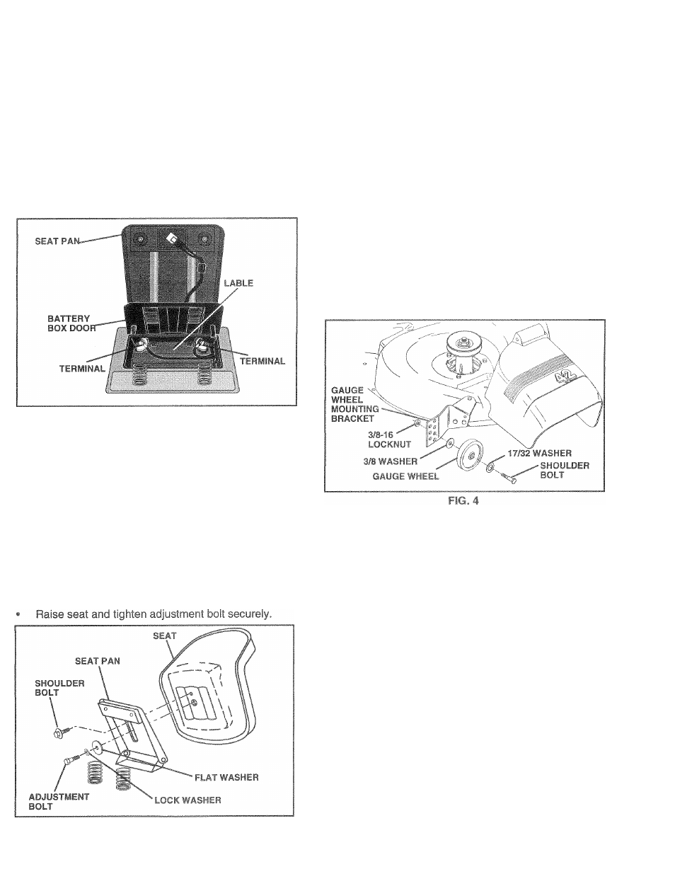
INSTALL SEAT (See Fig. 3)
Adjust seat before tightening adjustment bolt.
•
Remove cardboard packing on seat pan.
® Place seat on seat pan and assemble shoulder
bolt.Tighten shoulder bolt securely.
•
Assemble adjustment bolt, lockwasherand flat washer
loosely. Do not tighten.
•
Lower seat into operating position and sit on seat.
•
Slide seat until a comfortable position is reached which
allows you to press cluich/brake pedal all the way
down.
•
Get off seat without moving its adjusted position.
The gauge wheels ar
proper position wher
properly adjusted to c
jp the mower deck in
sr. Be sure they are
ire optimum mower performance.
h
I ‘ A t
(• ,
> . i.i'ih I 1
< 1 .,1 m l < t If v e '
;-;i!('
A d ju I r n ii ;< I ill < i in d ■ tiir.g ‘it-H h i I f-‘|.s A f> -
J l •* i F l
y J •
'J T s liL h L in ,r .!( ih i jp e ic -iio n
section of this manual).
With mower in desired height of cut position, gauge
!,h .Midi
' t d h ' , a. ,liyhiiyfif(he
gn 'ji'd liO-id'l i. 'I' (»
1
. I ' l l ..ppH p-mt" liuL with
shoulder bolt, 17/32 washer, 3/8 washer, and 3/8-16
k’l hull
1(1
f'(!hi-n
'
Ret.f li t-,r .,u! :• >!< nil ! isr.iliih'! fj • ig
in
sen If i.jjii'k.if'ik ii ;
R G . 3
CHECK TIRE Г
Thetire-s un y- u, if -Ur i i
‘irrl jtr-d at thefactoryfor
shipping puipu. i-s ' i
• Reduce tire pressure to PSI shown in “PRODUCT
SPECIFICATIONS” on page 3 of this manual.
CHECK СЕСКрГ/LlbT sF
For best! i.fiing'■esij't' т.о"-* I
k
ncnimhould be properly
ievele
DUSING” in the
Servic
nanual.
CHE
ON OF ALL
BELTS
See the figures that are shown for replacing motion and
mower blade drive belts in the Service and Adjustments
section of this manual. Verify that the belts are routed
correctly.
СНЕСИ
After you learn
h a . "
iu that the b ia k s i-'. - oTc-ied. oae ‘TO ADJUST BRAKE” in fl'c Tsi ,'ге d -.djusunrrts section of this manual.