MTD 24665L User Manual
Page 6
Attention! The text in this document has been recognized automatically. To view the original document, you can use the "Original mode".
t
. i i.-SH-ON
I
-. ..'NUTIT)
¿i'-
■
UH
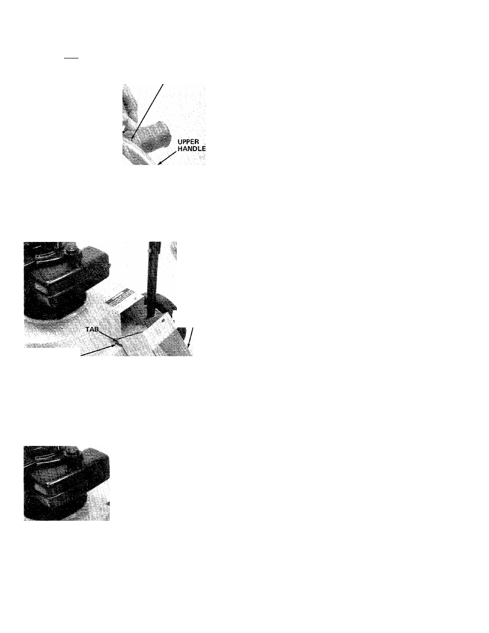
FIGURE?
STUD PIN (S)
9. Place the stud pins (S) in holes in upper handle
(head of pins go to the inside of handle). Secure
pins with push-on speed nuts (T) by holding
speed nut with box wrench and tapping pin with
hammer. See figure 7.
SLOT
%
DUC"
VelSSEMBLY
10. Place the tabs on the air duct assembly (D) into
the slots in the frame as shown in figure 8. Raise
the air duct into position.
FIGURE 8
^
*
THUMB
'SCREW (Q)
*' ..-BELLEVILLE
' VASHER(RI
*
11. Secure air duct with thumb screw (Q) and belle-
ville washers (R). Cupped side of washer must be
against the air duct. See figure 9.
FIGURE 9