Assembly, A warning, Introduction – Troy-Bilt 12090 User Manual
Page 6: Inspect unit, Step 1; unpacking instructions, Tools/materials needed for assembly, Step 2: attach handlebar, L(h>se parts list qty. description, Important
Attention! The text in this document has been recognized automatically. To view the original document, you can use the "Original mode".
Section
2
Assembly
A
WARNING
To prevent personal injury or property
damage, do not start the engine until
all assembly steps are complete and
you have read and understand the
safety and operating instructions in this
manual.
Introduction
Carefully follow these assembly steps to
correctly prepare your tiller for use. It is
recommended that you read this Section
in its entirety before beginning assembly.
NOTE: Various tiller models are presented
in this Manual. Use only the information
appropriate for your tiller model.
inspect Unit
Inspect the unit and carton for damage
immediately after delivery. Contact the
carrier (trucking company) if you find or
suspect damage. Inform them of the
damage and request instructions for filing
a claim. To protect your rights, put your
claim in writing and mail a copy to the
carrier within 15 days after the unit has
been delivered. Contact us at the Factory
if you need assistance in this matter.
STEP 1; Unpacking Instructions
NOTE: Do not severely bend any of the
control cables on the unit.
1. The tiller is heavy. Do not attempt to
remove it from the shipping platform until
instructed to do so in these Assembly
steps.
2.
Remove all unassembled parts from
the carton. The hardware bag is included
in your literature packaging.
3. If you ordered an Electric Start Tiller,
remove the hardware bag from under the
battery clamp (A, Figure 2-16).
4.
Check that you have the items listed
below (contact your local dealer or the
6
Factory if any items are missing or
(1)
Flat blade screwdriver
damaged).
(1)
Scissors (to trim plastic ties)
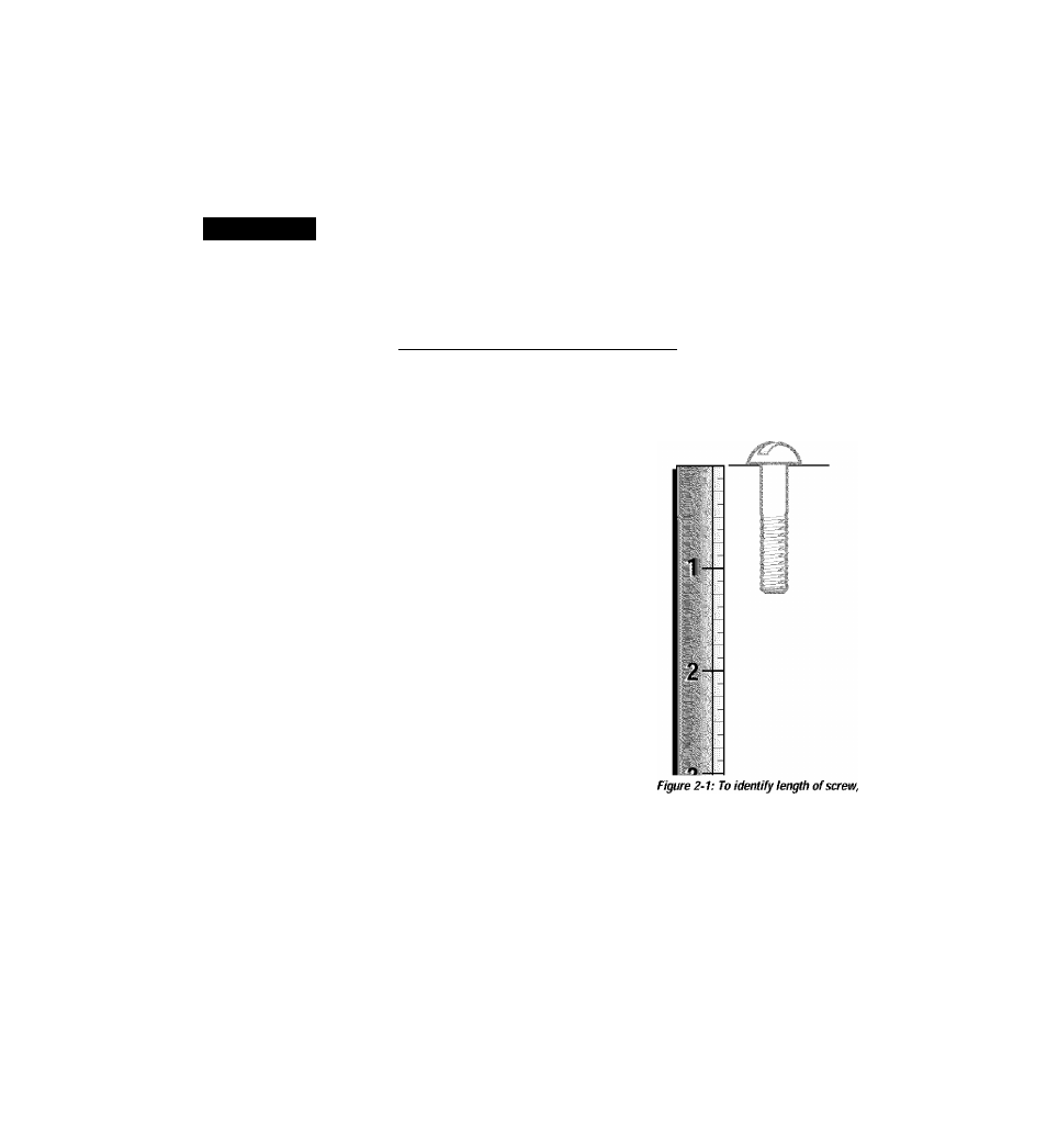
NOTE: Use the screw length template
(1) Tire pressure gauge
(Figure 2-1) to identify screws.
(1) Clean oil funnel
L(H>se Parts List
Qty. Description
(1)
Motor Oil. Refer to the Engine
Owner's Manual for motor oil spec
ifications and quantity.
1 Handlebar Assembly
1 Wheels/Tines PTO Drive Lever
(1)
4-1/2" high wood block (or other
sturdy block) to prop unit
The following items
are in the hardware bag:
1 Clutch Pawl Spring
*
Adjustable wrenches may be used.
1
Belt Adjusting Tool
2
Plastic Cable Ties
1 Curved Head Screw, 1/4-20 x 2
1 Flanged Lock Nut, 1/4-20
1
Pan Head Screw, #20-24 x 1/2
The following parts (electric start models
only), packaged separately, are located
under the battery clamp.
2
Nuts, 1/4-20
(for battery terminals)
2
Screws, 1/4-20x5/8
(for battery terminals)
1
Battery Vent Tube
2
Keys
(in ignition switch)
IMPORTANT:
Motor oil must be added to
the engine crankcase before the engine is
started. Follow the instructions in this
Assembly
Section and in the separate
Engine Owner's Manual.
NOTE: LEFT and RIGHT sides of the tiller
are as viewed from the operator's
position behind the handlebars (unless
otherwise noted).
Tools/Materials Needed
for Assembly
(1) 3/8" open-end wrench*
(2) 7/16“ open-end wrench*
(2) 1/2" open-end wrench *
(1) 9/16" open-end wrench *
(1) 3/4" open-end wrench*
place screw on template as shown and
measure distance between bottom of screw
head and tip of screw.
STEP 2: Attach Handlebar
IMPORTANT:
When
disassembling
handlebar assembly, keep left-side clamp
and ratchet separated from the right-side
clamp and ratchet.
1. Disassemble the handlebar assembly.
To do this, remove the height adjustment
lever by turning the lever in a counter
clockwise direction (Figure 2-2).