Note – MTD 112-162A User Manual
Page 5
Attention! The text in this document has been recognized automatically. To view the original document, you can use the "Original mode".
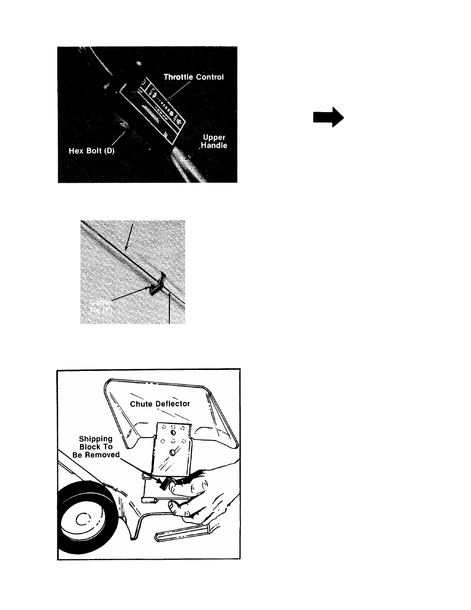
5. Place the throttle control in position on right
side of upper handle. Secure with hex bolt (D)
—and lock nut (E). See figure 4.
NOTE
Reference to right and left hand
sides of the unit is observed from
the operating position.
FIGURE 4.
6. Secure throttle control cable to upper and
lower handles with cable ties (F) provided. See
—figure 5.
7. Check ALL nuts and bolts for correct
tightness.
FIGURE 5.
A
CAUTION
Please note that the chute deflector
on your mower is in an upright posi
tion. It is held in that position by a
■shipping block. This block is used
for shipping purposes only. It must
be removed and discarded before
your mower is put into operation.
See figure 6.
FIGURE 6.