Extension, Maintenance, Lubrication – MTD 244-650A User Manual
Page 3: Before starting, Note, Caution, Figure 4
Attention! The text in this document has been recognized automatically. To view the original document, you can use the "Original mode".
EXTENSION
A steady flow of material provides the best results.
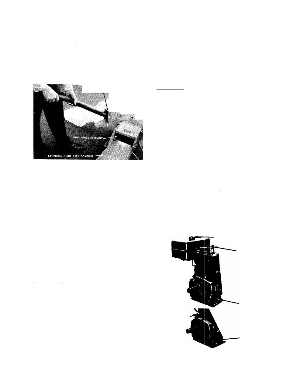
Bulky material, such as stalks or heavy branches, should
be fed into the upper guide extension. See figure 3.
When sharpening blade, follow the original angle of
grind as a guide. It is extremely important that each
cutting edge receives an equal amount of grinding to
prevent an unbalanced! blade. An unbalanced blade
will cause excessive vibration when rotating at high
speeds and may cause damage to the unit. Upon reas
sembly, make certain a I parts are assembled properly
and tightened securely.
UPPER GUIDE EXTENSION
ELASTIC LOCK NUT
FIGURE 3. FEEDING MATERIAL INTO UPPER GUIDE
EXTENSION
It is possible to feed too fast and you will find it will
take some experimenting with feeding rates to get
the most out of your shredder without stalling the en
gine.
Under certain conditions, it may be necessary to push
the materials into the inlet guide assembly. When this
becomes necessary, use a small diameter stick—NOT
YOUR HANDS. The stick should be of a size that will be
ground up if it gets into the impeller assembly.
The discharge chute will direct the shredded material
into a pile or a container. NOTE: Your shredder is
equipped with a nylon bag with drawstring lock. This
will accommodate a perforated disposable plastic bag.
CAUTION: Keep clear of the chute area since the
shredded material comes out with considerable velo
city. Always stop engine and disconnect spark plug
wire when changing bags.
MAINTENANCE
CAUTION: Always stop engine and disconnect spark
plug wire before doing any maintenance.
Cutting Blade—The blade may easily be removed for
grinding or replacement as follows:
1. Remove guide extension assembly by removing
four elastic locknuts (Ref. No. 11). See figure 8.
2.
Remove bolt (Ref. No. 38), lockwasher (Ref. No.
37) and flat washer (Ref. No. 36) holding blade
(Ref. No. 45) to engine crankshaft. See figure 9.
3. NOTE: Blade is reversible and can be assembled
to crankshaft with either side showing.
LUBRICATION
WHEELS—Wheel bearings are of lifetime Fortiflex. They
require no lubrication.
ENGINE—Follow engine manual for lubrication instruc
tions.
«•
u
o
O
o
o
0
< >
1
I
CAUTION
Do Not deposit material larger
than y?" diameter in hopper.
This may cause damage to the
shredding mechanism.
BEFORE STARTING
NOTE
Do not mix oil with gasoline.
1. Fill fuel tank with fresh regular gasoline. (See fig
ure 4.)
2. Fill crankcase with oil. (See figure 4.)
Oil Dip Stick
Fili with regular gasoline
Shorting Clip
Drain Plug
Oil Filler Plug
Drain Plug
FIGURE 4.