To stop engine, How to use your tiller, Wheel position – MTD 213-381A User Manual
Page 8: Hairpin ‘ti cotter, Clevis pin '' spring pi, Figure 15, Controlling speed and tilling depth, Figure 16
Attention! The text in this document has been recognized automatically. To view the original document, you can use the "Original mode".
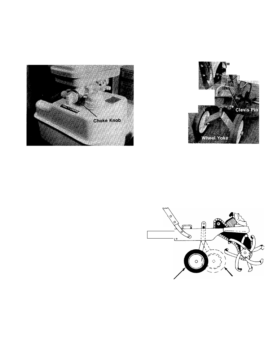
2. Pull choke knob out to choke engine. See
figure 14.
H^NOTE
Warm engine does not require chok
ing.
FIGURE 14.
3.
Move
throttle
control
lever
forward
to
“START” position. See figure 12.
4. Stand at side of the tiller. Grasp the starter
handle and pull out rapidly. Return it slowly to
the engine. Repeat if necessary.
5.
After engine starts, push choke knob in
gradually to “OFF” position.
TO STOP ENGINE:
1. Move throttle control lever to “STOP” posi
tion. See figure 12.
2. Remove spark plug wire from spark plug to
prevent accidental starting while equipment
is unattended.
HOW TO USE YOUR
TILLER
The tiller is a precision built machine designed for
seed bed preparation, cultivating, furrowing and
mulching. It is engineered to minimize the hardest
work in the vegetable or flower garden, to till the
soil for planting and cultivating, and to perform
many other useful labor saving tasks in the
garden. With the proper amount of care and
maintenance, this machine will provide the owner
with many years of excellent service.
WHEEL POSITION
The tiller is shipped with the wheels adjusted
such that the unit sits level. During digging as the
tines enter the ground and the front of the tiller
lowers, the wheels must be raised to level the
unit. This is essential for proper engine operation.
This adjustment is made by removing the clevis
pin and hairpin cotter from wheel yoke, raising the
wheels to the desired height, and replacing the
clevis pin and hairpin cotter. See figure 15.
\ Hairpin
‘ti Cotter
Clevis Pin '' Spring Pi
Depth Bar
FIGURE 15.
CONTROLLING SPEED AND TILLING DEPTH:
1. Wheel Yoke Adjustment: Place wheel yoke so
that the wheels are forward (nearest point be
tween wheels and tines) for shallow tilling,
cultivating and transport. This will increase
the forward speed. See figure 16. Turn yoke
around (farthest point between wheels and
tines) for deep tilling. Forward speed will
decrease. See figure 16.
\ o \
•
Wheel Yoke in
this position
for deep dig.
FIGURE 16.
Wheel Yoke in this
position for shallow
dig, cultivating and
transport.
2. Depth Bar Adjustment: The depth bar acts as
a brake for the tiller and controls the depth
and speed at which the machine will operate.
See figure 17. Remove the clevis pin and
spring pin to raise or lower depth bar.