Assembly instructions, Note, Tailpiece installation – MTD 213-381A User Manual
Page 4
Attention! The text in this document has been recognized automatically. To view the original document, you can use the "Original mode".
Handle
Assembly
Control
Rod
ASSEMBLY INSTRUCTIONS
Depth Bar
FIGURE 1.
FIGURE 2.
‘U” Clevis
Pin (A)
Frame
Taiipiece
NOTE
This unit is shipped WITHOUT GAS
OLINE or OIL. After assembly, see
operating section of this manuai for
proper fuel and engine oii recom
mendations.
Before any step is undertaken, the instructions for
that step should be read thoroughly.
Tools Required:
(2) 9/16" Sockets, open or box wrench
(1)
1
/
4
" Flat Screwdriver
(1) Hammer
-Loose Parts in Carton: (See Figure 1)
Handie Panei Assembly
Depth Bar
Tailpiece
Control Rod
Hardware Pack (Not Shown)
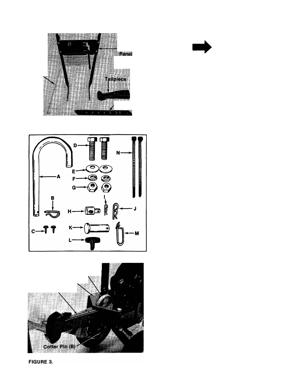
-Contents of Hardware Pack: (See Figure 2)
A (1) “U”-Clevis Pin .50" Dia.
B (1) Internal Cotter Pin
C (2) Self-Tapping Screws
D (2) Hex Bolts 3/8-16 x 1.00" Lg.
E (2) Belleville Washers 3/8" I.D.
F (2) Lock Washers 3/8" I.D.
G (2) Hex Nuts 3/8-16 Thd.
H (1) Ferrule
I (1) Hairpin Cotter
J (1) Hairpin Cotter
K (1) Clevis Pin
L (1) Throttle Control Knob
M (1) Spring Pin
N (2) Cable Ties
O (2) Grips (Not Shown)
P (2) Carriage Bolts (Not Shown)
Q (2) Lock Washers 5/16" I.D. (Not Shown)
R (2) Hex Nuts 5/16-18 Thd. (Not Shown)
TAILPIECE INSTALLATION
Slide the tailpiece into the frame. Secure with
■“U”-clevis pin (A) and cotter pin (B). See figure 3.