Troy-Bilt 12001C User Manual
Page 11
Attention! The text in this document has been recognized automatically. To view the original document, you can use the "Original mode".
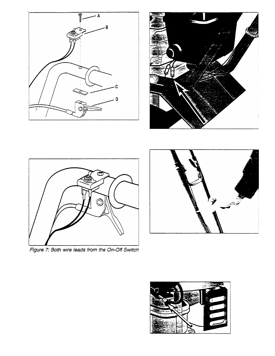
Figure 6: Installing Engine On/Off Switch (B) and
Throttle Lever Assembly (D) to right handlebar.
16. Two wire leads come from the top of the
On/Off switch assembly. See Figure 7. Each
wire has a different color connector.
must be connected to their corresponding en
gine leads.
17.
Oonnect the loose ends of these two wire
leads to the two loose wires shown in Figure 8.
Plug the matching color connectors together.
Red connector to red connector, and white con
nector to white connector.
18. Secure the throttle cable and the Engine
Ignition On/Off switch wires to both the lower and
the upper handlebars with the plastic ties (Photo
9). The serrated side of the ties should be on
the inside when you loop the tie around the han
dlebar, wire, and throttle cable. Tighten the tie
by pulling on its loose end. Snip off excess.
Figure 8: Snap together the two sets of wires
having the same connector colors.
Photo 9: Install plastic ties to keep the cables
next to the handlebars.
19. Inspect and tighten ail hardware using regu
lar household tools. IMPORTANT: Do Not
Tighten
Or
Adjust
The
Engine
Governor
Screw Shown in Figure 9A. It Is Factory-
Adjusted For Proper Engine Operation!
Figure 9A:
Do not
adjust or
tighten the
factory-set
governor
speed screw
(see arrow).
11