Assembly steps – Troy-Bilt 12001C User Manual
Page 10
Attention! The text in this document has been recognized automatically. To view the original document, you can use the "Original mode".
ASSEMBLY STEPS
You’ll need the following tools for assembly:
• Two 7/16" wrenches ( a 7/16" socket, exten
sion, and ratchet can be substituted for one
of the 7/16" wrenches).
• One Medium size Phillips head screwdriver.
1. Unwind the throttle cable from around the en
gine. Use care when unwinding the cable so it is
not kinked or bent.
2. Place the engine/tines/transmission assembly
so it is resting on its “face" (the product name
logo label is face down).
3. Place the lower left handlebar on the left side
of the transmission (below the engine— above
the tine cover). Align the two holes in the lower
handlebar with the two holes in the transmission.
Photo 3: Attaching Lower Left Handlebar.
4. Install a fiat washer on the two long (5”) hex
head screws provided in the hardware bag.
Insert the two screws through the lower left han
dlebar and out the right side of the transmission.
See Photo 3.
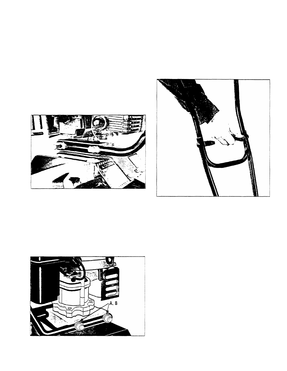
5. Place the lower right handlebar over the ends
of the screws on the right side of the transmis
sion. See Figure 4. Add a fiat washer (A, Figure
4) and locknut (B) to each screw.
6. Evenly tighten the two screws and locknuts
that secure the lower handlebars. Snug the nuts
down until tight, but do not overtighten them.
7. Place the upper handlebar between the top
ends of the two lower handlebars.
8. From the outside, slide one of the curved
head carriage bolts through the left handlebar.
(Photo 5).
9. Place a flat washer over the end of this bolt.
Install a handlebar knob on the carriage bolt.
See Photo 5.
Photo 5: Attach Upper Handlebar to Lower
Handlebars.
10. Repeat steps 8 and 9 for the other side.
11. Tighten both handlebar knobs.
12. Slip the throttle lever mounting screw (A,
Figure 6) down through the hole in the Engine
Ignition On/Off Switch bracket (B, Figure 6).
Then insert the screw down into the hole that is
in front of the right handlebar grip. Note that the
switch and bracket are to the inside of the right
handlebar.
13. Place the rectangular rubber throttle lever
spacer (C) over the end of the screw (turn
spacer so its “long” end points to the rear).
14. Position the Engine Throttle Lever assembly
(D) on the end of the screw.
15. Hold the Throttle Lever Assembly In place.
After you’ve started the screw, use a Phillips
head screwdriver to firmly tighten it. See Figure 6.
Figure 4: Install Lower Right Handlebar. Secure
with two flat washers (A) and two locknuts (B).
10