Adjustments, Seat, Neutral setting – Ariens 912 User Manual
Page 20: Rider brake
Attention! The text in this document has been recognized automatically. To view the original document, you can use the "Original mode".
Adjustments
Arieris Company recommends that you have ad
justments made by your Ariens dealer. He has
tools and the know how to properly perform ad
justments which may be required to keep your
riding mower operating at peak efficiency.
Should you decide to make the foilowing ad
justments on your riding mower yourseif, Ariens
Company recommends that you call your dealer
for answers to any questions that might arise.
For ease of access to bottom of unit during
lubrication and maintenance procedures, your
riding mower may be driven up on ramps or tip
ped up onto bagger attachment service bar and
braced securely. (For units without a bagjger at
tachment, a service bar package is available
through your Ariens Dealer.)
A
CAUTION: Refer to instructions in begin
ning of Lubrication and Maintenance
Section when tipping riding mower.
A
A
WARNING: Stop engine, remove key,
wait for moving parts to stop and remove
wire from spark piug before attempting
any adjustment procedures.
CAUTiON: DO NOT touch engine or
riding mower parts which are hot from
operation. Aiiow such parts to cooi
before servicing unit.
Seat
Adjust seat to suit operator by loosening cap
screw under seat, sliding seat to a safe com
fortable operating position with operators
feet on footrest, and tighten cap screw.
NOTE: Operating unit with feet on mower pan,
besides being dangerous, will keep pan from
floating and will result in uneven cut.
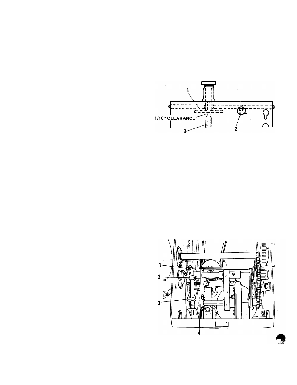
Neutral Setting
With Speed Selector in neutral (N) and clutch
pedal released, there must be 1/16” clearance
between friction wheel and drive plate.
NOTE: Rotate friction wheel when checking for
1/16” clearance between drive disk and friction
wheel.
To adjust, turn adjustment screw (accessable
through hole in rear frame) to obtain proper . ^
clearance. After adjusting neutral setting, ad
just Rider Brake according to following in
structions.
1. Drive Disk
2. Adjustment Screw
3. Friction Wheel
Figure 13: Neutral Setting
Rider Brake
Clutch and brake adjustments are dependent
upon each other. With Speed Selector in any
forward speed, depress clutch pedal until fric
tion wheel just clears drive disk. (Clutch Pedal
can be held in this position with Parking Brake
latch.)
1. Brake Rod
2. Brake Set Collar
3. Brake Band
4. Brake Drum
Figure 14: Rider Brake
18