MTD 217-310-000 User Manual
Page 6
Attention! The text in this document has been recognized automatically. To view the original document, you can use the "Original mode".
3
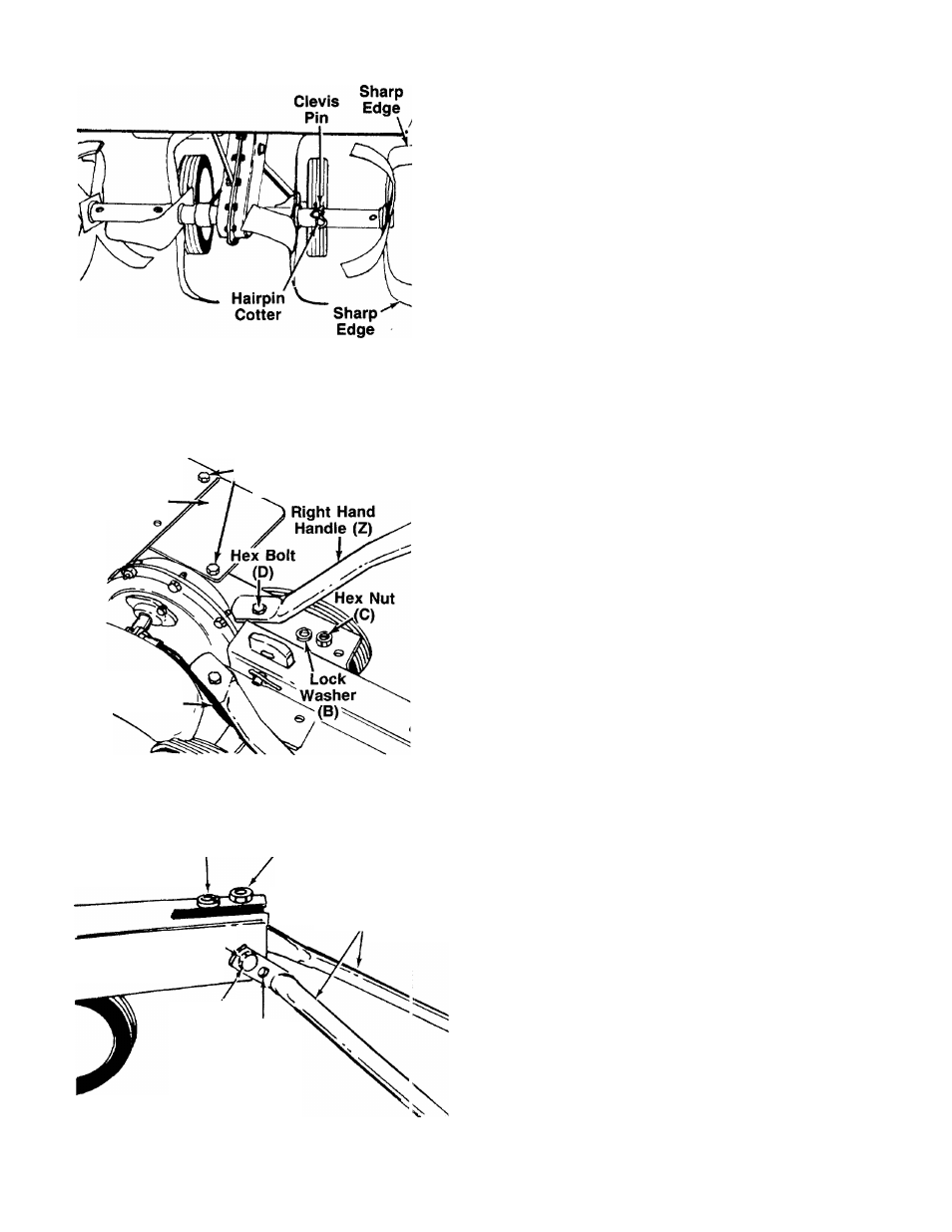
7. Remove the clevis pin and hairpin cotter from the
— inner tine assemblies as shown in figure 7. Place
the right and left hand tine assemblies in position
on tine shaft. Secure with clevis pins and hairpin
cotters.
■i^NOTE
Be certain the tine assemblies are
assembled on the tine shaft so that
the sharp edge of the tines enter the
soil first. See figure 7.
FIGURE 7.
Tine
Shield
Extension
(AD)
Hex Bolts (Q)
/Lock Washers (R)
Hex Nuts (S)
Left Hand
Handle (AA).
8. Attach the tine shield extension (AD) to the tine
shield and frame on the right side of the unit as
— shown in figure 8. Secure with hex bolts (Q), lock
washers (R) and hex nuts (S). Tighten securely.
9. The left handle has a clutch grip already assem
bled to it. Assemble the left and right hand handles
(AA and Z) to the rear tiller frame as shown in figure
8. Secure with hex bolts (D), lock washers (B) and
hex nuts (C), finger tight only (do not tighten).
FIGURE 8.
Lock Washer (B) Hex Nut (C)
Handle
Braces (U)
Hex Bolt (D)v
©
High
Position Low
Position
10.-- Attach the right and left hand braces (U) to the
tailpiece. The braces have two holes to provide
handle height adjustment Select hole for either
high or low position. Secure to tailpiece with hex
bolts (D), lock washers (B) and hex nuts (C), finger
------ tight only (do not tighten). See figure 9.
FIGURE 9.