Assembly instructions – MTD 217-310-000 User Manual
Page 4
Attention! The text in this document has been recognized automatically. To view the original document, you can use the "Original mode".
NOTE
Reference to left or right side of the
tiller is determined from behind the
unit in the operating position.
ASSEMBLY INSTRUCTIONS
NOTE
FIGURE 2.
This unit is shipped WITHOUT GAS
OLINE or OIL. After assembly, see
separate engine manual for proper fuel
and engine oil recommendations.
Tools Required:
(2) Va" Wrenches
(2) 7/16" Wrenches
(1) %" Wrench
(1) Adjustable Wrench
(1) Phillips Screwdriver
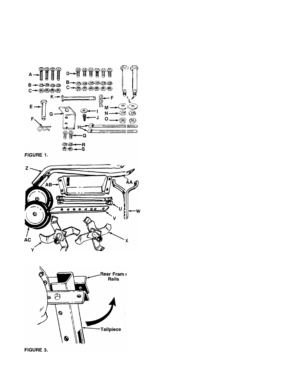
-Contents of Hardware Pack: (See Figure 1)
A (4) Carriage Bolts 5/16-18 x 1%" Long
B (10) Lock Washers 5/16" I.D.
(10) Hex Nuts 5/16-18 Thread
(6) Hex Bolts 5/16-18 x W Long
(1) Clevis Pin Va" x 2Va" Long
(2) Hairpin Cotters
(1) Clutch Cable Support Bracket
(2) Cable Ties
(1) Flat Washer
(1) Hex Washer Head Self-Tapping Screw
Va" Long
(1) Clevis Pin 3/8"
X
2Va" Long
(2) Shoulder Bolts (Axles)
(2) Belleville Washers
(2) Lock Washers Va" I.D.
(2) Hex Nuts Va-20 Thread
(2) Grips (Not Shown)
(2) Hex Bolt V4-20 x 5/8" Long
(2) Lock Washers V4" I.D.
(2) Hex Nuts V4-20 Thread
(1) Phillips Head Self-Tapping Screw Va" Long
(Not Shown)
-Loose Parts in Carton: (See Figure 2)
U
V
w
X
Y
z
AA
AB
AC
AD
C
D
E
F
G
H
K
L
M
N
O
P
Q
R
S
T
(
2
)
(
1
)
Handle Braces (Right & Left Hand)
Depth Bar
(1) Wheel Yoke Assembly
(1) Right Hand Tine Assembly
Left Hand Tine Assembly
Right Hand Handle
Left Hand Handle
Handle Panel
Wheels
(
1
)
(
1
)
(
1
)
(
1
)
(
2
)
(1) Tine Shield Extension (Not Shown)
1. Remove the tiller, all loose parts and literature from
the carton before discarding carton.
2. Extend the throttle control and place on the floor.
Be careful not to bend or kink control wire.
-3. The tailpiece is partially assembled. Pivot the
tailpiece upward until the holes line up with the rear
frame rails. See figure 3.