Maintenance, Brake adjustment, Hydrostatic neutral adjustment – Troy-Bilt 13027 User Manual
Page 29: Hydrostatic drive adjustment, Drive belt removal and installation
Attention! The text in this document has been recognized automatically. To view the original document, you can use the "Original mode".
Maintenance
Brake Adjustment
When the brake will no longer
hold the tractor with the brake lock
engaged, an adjustment is required.
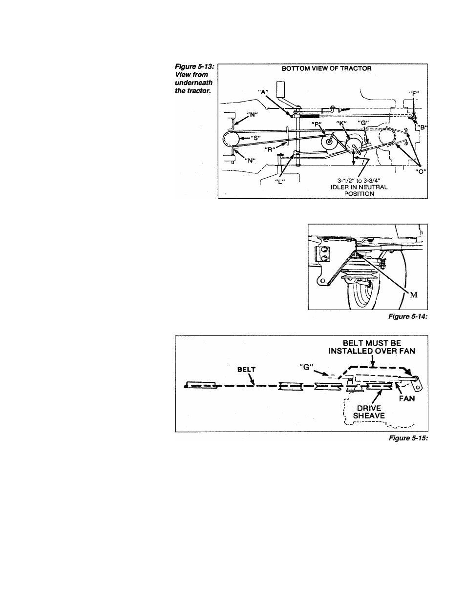
Locate nut “A” (Figure 5-13) on
the brake rod. Adjust the nut until
the rod end (“B”, Figure 5-13) is in
the center of the slot in the arm
(“F”).
When you have finished making
this adjustment, be sure to check
the brakes for proper braking.
Hydrostatic Neutral Adjustment
If the tractor ‘creeps’ when the
Travel Pedal is in the Neutral posi
tion (foot off the pedal), an adjust
ment is required. Do not use the
tractor in this condition. Please
contact your Authorized Dealer to
have this adjustment performed.
Hydrostatic Drive Adjustment
With the brake pedal depressed,
engage the Parking Brake knob.
Now check the distance between
idler pulley “K” (Figure 5-13) and
the frame wall. This dimension
should be between 3-1/2" and 3-
3/4". If an adjustment is required,
adjust at pivot “L”, Figure 5-13.
Note: The belt should not creep
when Parking Brake is engaged
and engine is running at high RPM.
Drive Belt Removal
And Installation
1. Cut and remove the old belt.
2. Loosen the electric clutch locat
ing retainer (“M”, Figure 5-14).
3. Loosen belt guides (“N”, Figure
5-13).
4. Remove ball joint (“G”, Figure
5-13).
5. Use only a genuine replacement
belt- do not use a substitute.
Route the new V-belt up and over
the fan (Figure 5-15) and then
down until it rests in the pulley
groove. It will be necessary to
loosen and reposition belt guides
(“O”, Figure 5-13) to install. Re
tighten guides when V-belt is in
place.
6. Route V-belt around idlers “K”
and “P”, Figure 5-13. Belt guides
must be moved slightly to assemble.
7, Position V-belt between rod “R”
in Figure 5-13 and place over en
gine pulley “S”.
8, Retighten the electric clutch lo
cating retainer (“M”, Figure 5-14).
9, With the Brake Pedal disen
gaged, check that the belt guides at
idler pulleys “K” and “P” in Figure
5-13 are in the position shown.
10. Check that belt guides “O” on
the hydrostatic drive pulley are
within 1/16" to 1/8" of the belt.
11. Check that belt guides “N” in
Figure 5-13 are within 1/8" to
3/16" of the electric clutch sleeve
(“S”).
12. After assembly check
Hydrostatic Drive adjustment.
29