Interlock safety switch system, Warning, Steering adjustment – Troy-Bilt 13027 User Manual
Page 28
Attention! The text in this document has been recognized automatically. To view the original document, you can use the "Original mode".
Interlock Safety Switch System
Your tractor is equipped with
three (3 ) electrical Interlock
Safety Switches that are always
functioning simultaneously. Their
purpose is to shut the tractor en
gine off immediately by grounding
the electrical system if any of sev
eral unsafe operating conditions is
present. The Interlock Safety
Switches are described below.
1. One interlock safety switch is
located in the PTO Attachment
Drive Switch system. The engine
will not start if the PTO Drive
Switch is in the “On” position.
The PTO Drive Switch must be
moved to “Off’ before the engine
will turn over.
2. The second interlock safety
switch is located underneath the
operator’s seat. The operator must
be sitting in the seat before the en
gine can be started. Also- if the
operator should leave the seat
while the engine is running and
does not turn the PTO Attachment
Drive Switch to “Off’ and engage
the Parking Brake, the engine will
shut off automatically.
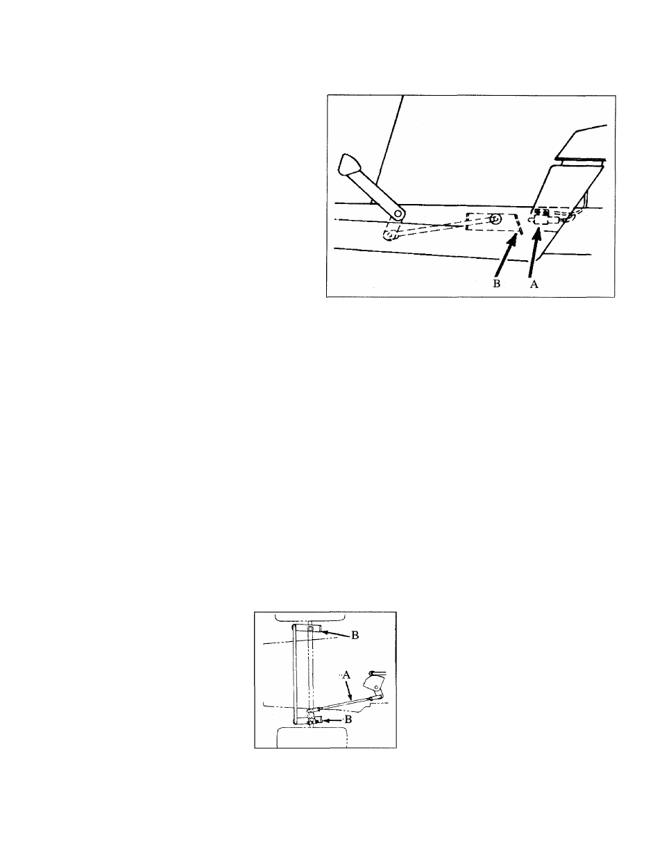
3. The third interlock safety switch
is located as shown in Figure 5-11,
“A”. It prevents the engine from
starting if the Brake Pedal is not
fully depressed manually (or held
down by the engaged Parking
Figure 5-11:
This is the
third of three
interiock
safety
switches (“A”)
on your trac
tor. The three
switches are
iinked to the
operation of
the Brake
Pedai, the op
erator’s seat,
and the PTO
Attachment
Drive Switch.
The engine
wili not start uniess the PTO Attachment Drive Switch is “Off” and the Brake
Pedai is depressed (or Parking Brake is engaged). When the engine is run
ning, the operator must shut off the PTO Attachment Drive Switch and en
gage the Parking Brake before ieaving the seat or the engine wiil stop.
Brake) during the engine starting
procedure. If the bracket (“B”,
Figure 5-11) next to the interlock
switch does not depress the
plunger of the switch when the
Parking Brake lever is engaged,
have your Authorized Dealer make
an adjustment to the safety switch.
WARNING
Before performing any main
tenance on the tractor or the
engine, the tractor must be
stopped, the PTO switch shut
Off, the Parking Brake en
gaged, the engine stopped
and the key removed, and the
spark plug wire must be dis
connected
and
kept
away
from the plug. Always let en
gine and muffler cool down.
Failure to comply can result
in serious personal injury or
property damage.
Steering Adjustment
When the steering wheel has
been turned fully to either the right
or the left, the spindle stop (“B”,
Figure 5-12) of the steering arm
should make contact with the front
axle. “A” is the adjustment rod. If
an adjustment is necessary, please
contact your Authorized Dealer for
this service. This is a very impor
tant adjustment that your Dealer is
highly qualified to make.
Figure 5-12: Steering adjustment.
28