SINGER 29K73 User Manual
Page 17
Attention! The text in this document has been recognized automatically. To view the original document, you can use the "Original mode".
15
TO EXAMINE, REMOVE AND RE-ASSEMBLE THE
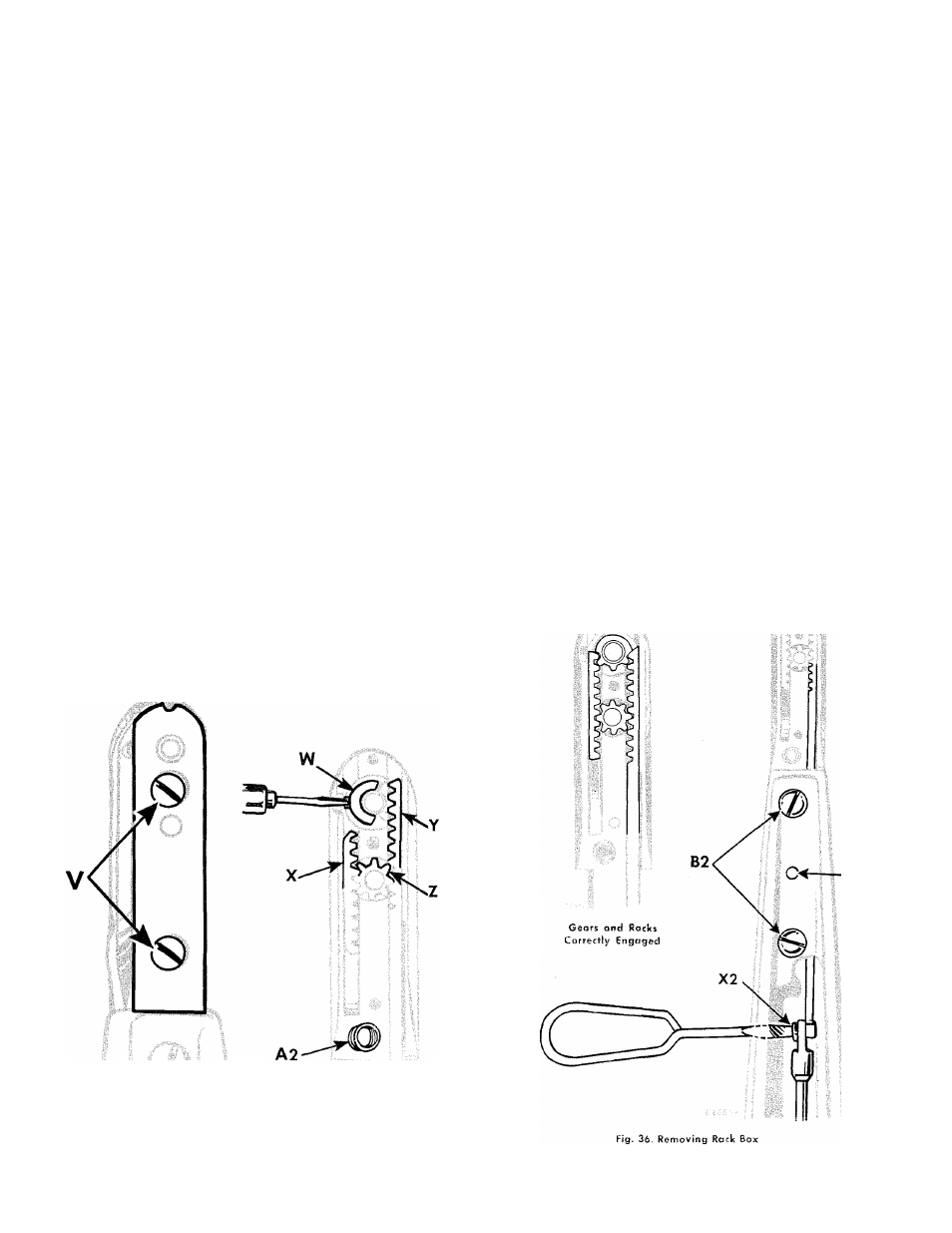
PARTS FROM THE RACK BOX
Remove machine from treadle stand or power bench
after taking out the four screws located at the base of
the machine. The machine should then be tilted back
upon its machine pulley end, the underside facing the
adjuster. Parts can be examined or removed from the
rack box after taking out the two screws V, Fig. 34
and removing the cover plate. The following parts are
then exposed as shown in Fig. 35: long rack Y, short
rack
X,
intermediate
pinion
Z,
shuttle
driving
pinion
W,
needle
plate
locating
pin
and
spring
A2,
all
of
which can be removed without disconnecting the rack
box from the machine.
To take out the shuttle carrier, remove the small set
screw in the shuttle driving pinion W by inserting a
small
screwdriver
through
the
groove
at
the
side
of
the rack box as shown in Fig. 35. The shuttle carrier
can then be pressed through the pinion. To remove the
long
rack
Y,
insert
a
screwdriver
through
hole
as
shown in Fig. 36 and take out the screw X2. Before
proceeding
to
withdraw
the
rack,
remove
the
pinion
Z, Fig. 35 then grip the rack and draw it straight
toward the pulley end of the machine. The short rack
X and shuttle driving pinion W can be removed with
out difficulty. When replacing any one or re-assembling
the whole of these parts, care must be taken to see
that
the
gears
and
racks
are
correctly
engaged,
as
shown in Fig. 36.
INSTRUCTIONS FOR REMOVAL OF THE
RACK BOX
If for any reason it is necessary to remove the rack
box from the machine, proceed as follows: Remove the
machine from its treadle stand or power bench. Turn
the hand wheel until the connecting rod hinge screw
X2, Fig. 36 is opposite the hole in the lower arm. Then
tilt the machine isack upon its machine pulley end, the
underside
facing
the
adjuster.
Insert
a
screwdriver
through the hole as shown in Fig. 36, and remove the
screw X2. Slightly loosen the two screws B2 by giving
them a half turn with a screwdriver. Then drive out
the taper pin C2, using a 3/16" punch and hammer,
and take out the two screws B2. The machine should
now be replaced on its, feet and the horn will then
come away if pulled in a horizontal direction.
CAUTION: Never raise the front of the horn or the
end of the long rack may be damaged.
When
re-assembling
the
box
to
the
machine,
be
sure that the taper pin C2 is driven in as far as it will
go before finally tightening the two screws B2, Fig. 36.
NOTE: Cover plate is shown removed in Fig. 36 to
illustrate how the gears and racks should be correctly
engaged.
Fig, 34. Removing
Cover Plate
Fig, 35. Removing Parts
from Rack Box