SINGER 29K73 User Manual
Page 14
Attention! The text in this document has been recognized automatically. To view the original document, you can use the "Original mode".
12
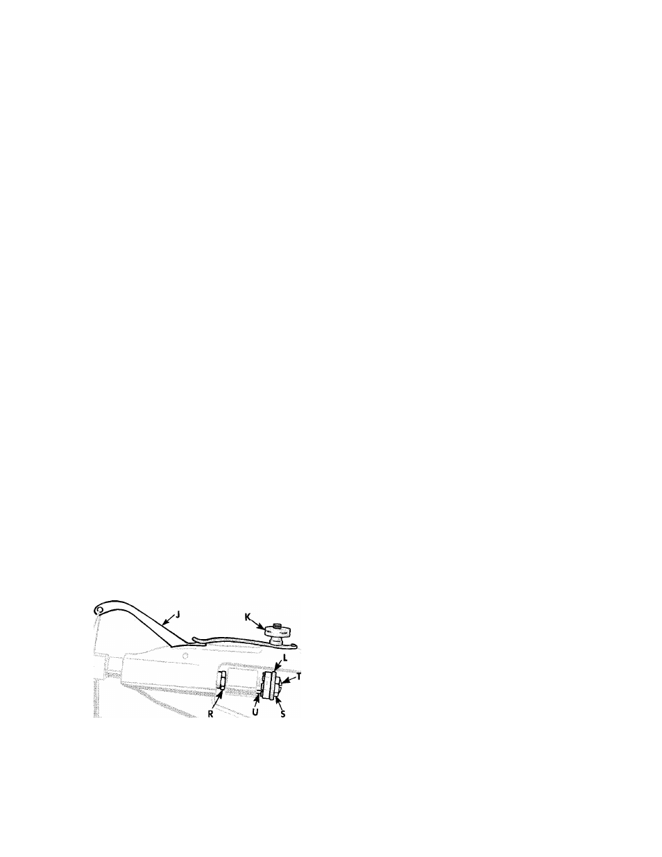
Td REGULATE THE TAKE-UP LEVER
WITH REGULATOR INDICATOR
The spring tension on take-up lever J, Fig. 29 is
adjusted by thumb nut K. The tension on this lever
should be about the same as that applied to the upper
thread by the tension discs.
When the stitch is set, at the top of the needle bar
stroke, lever J should be held down far enough by the
tension of the thread so that the take-up action will
keep the thread taut until the needle enters the work.
When
sewing
light
weight
materials
with
fine
thread, more take-up action may be secured by turn
ing the thumb nut K so that it screws up to decrease
the take-up spring tension. This should be done instead
of tightening the thumb nut of the tension discs.
For heavier materials and thread, the take-up ten
sion must be about the same as that applied to the
upper thread by the tension discs.
The travel of take-up lever J is regulated by means
of knurled nut L. The indicator near nut L is marked
with the figures 0 to 4. This indicator provides a useful
guide to the operator in setting the take-up movement
most suitable for the material and thread being used.
For thin materials, such as kid or box calf, turn knurled
nut L until the zero mark is opposite the small plunger U.
Other adjustments can be made in steps by turning
the nut to suit any thickness of material and thread
within the capacity of the machine.
NOTE: All machines sent out from the factory are
so adjusted that they will give satisfactory results on
a
general
range
of
materials.
Before
any
adjustment
is made to the travel of the take-up lever, the needle
bar should be raised to its highest point.
ADJUSTMENT OF THREAD TAKE-UP LEVER
REGULATOR INDICATOR
The
range
of
adjustment
given
by
the
indicator,
when sent out from the factory, should suffice for all
general
purposes,
but,
if
desired,
the
range
can
be
raised
or
lowered
by
means
of
the
adjusting
screw
T, Fig. 29 at the extreme right.
To alter the range, loosen the lock nut S and, using
a screwdriver, turn the center screw T to the right to
reduce the travel of the take-up lever.
To increase the travel, turn the screw T to the left.
Wear at the tip of the center screw can also be taken
up in this manner. When the proper adjustment has
been obtained, tighten the lock nut S.
It is most important that the hexagon head nut R
be securely locked against the face of the piston.
TO CHANGE LENGTH OF STITCH
The length of stitch is regulated by the stitch regu
lator
which
is
held
in
position
by
thumb
screw
M, Fig. 30 at back of the feeding foot bar. Loosen
thumb screw M and move the regulator up or down
until its top is in line with the mark indicating desired
number of stitches to the inch as shown by the arrow.
Then tighten the thumb screw.
Ms.
Fig. 29. Regulating Tension and Travel of Take-up Lever
Fig. 30. Changing Stitch Length