Thread controller, To adjust the thread controller, To see if the needle bar is set correctly – SINGER 142W25 User Manual
Page 8: Adjusters and machinists
Attention! The text in this document has been recognized automatically. To view the original document, you can use the "Original mode".
12
I N S T R U C T I O N S
FOR
ADJUSTERS AND MACHINISTS
Thread Controller
The function of the thread controller spring Is to hold back
the slack of the needle thread until the eye of the needle
reaches the goods In Its descent, as without this controlling ac
tion of the spring, the slack thread or silk (more especially
silk) will sometimes be penetrated by the point of the needle as
the needle Is descending.
To Adjust the Thread Controller
For more controller action on the thread, loosen the stop
screw (N,Fig.16) at the right of the tension and set the stop
lower, and for less action, set the stop higher.
N 0
F521/
Fig. 16. Adjustments of Thread Controller
To strengthen the action of the controller spring on the
thread, loosen the tension stud screw (0,Fig.16) at the right of
the stop screw and turn the tension stud slightly to the left
with a screwdriver, or to lighten Its action on the thread, turn
the tension stud to the right and tighten the tension stud screw
(
0
) .
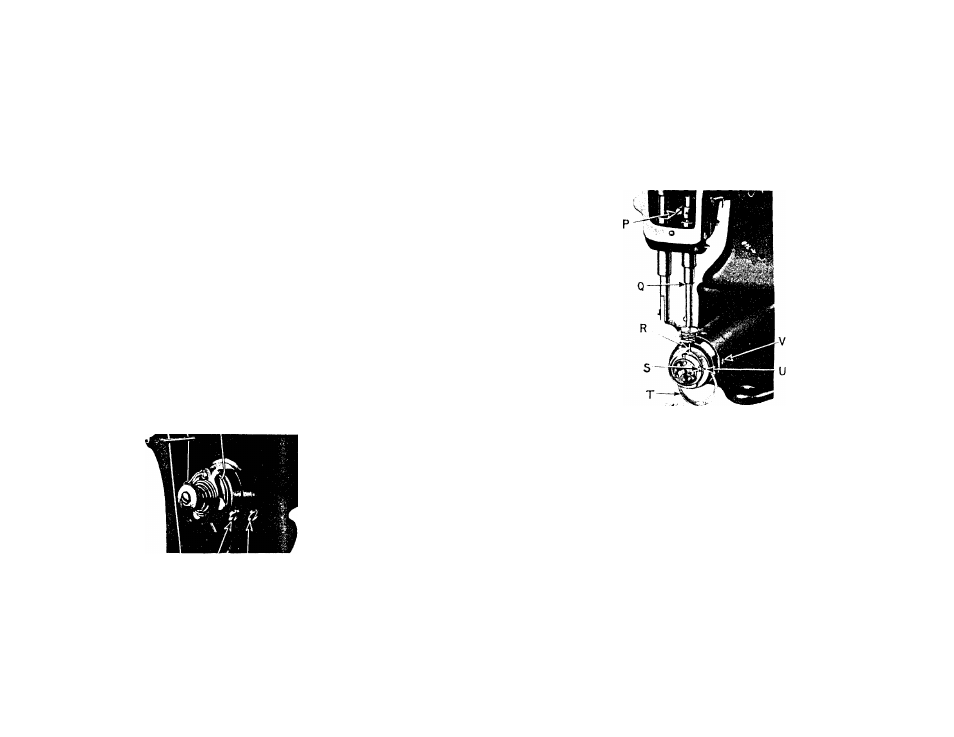
To See if the Needle Bar is Set Correctly
See that the needle Is up In the bar as far as It will go.
The needle bar which Is In the machine when shipped from the
factory has upon it (about 1 1/2 Inches from the bottom) two
lines 3/32 Inch apart.
When the needle bar Is at Its lowest position, the upper
mark should be Just visible at the end of the bushing.
13
Fig. 17. Needle Bar and Hook Adjustments
TO SET THE NEEDLE BAR IN CORRECT TIME. Loosen the needle bar
connecting stud pinch screw (P,Fig.17) and place the needle bar
in the proper position as directed above, then retlghten the
screw.
TO SET A NEEDLE BAR WHICH HAS NO MARK. Set the needle bar so
that when It rises 3/32 Inch from Its lowest position and the
point of the hook Is at the center of the needle (see R,Fig.17),
the eye of the needle will be about 1/16 Inch below the hook
point.
To See if the Hook is Correctly Timed
Take out the screw (E,Flg.6) and remove the cylinder end
cover (F,Flg.6). Turn the balance wheel toward you until the
lower mark (Q,Fig.17) across the needle bar, as it Is going up.
Is Just visible at the end of the bushing; now. If the needle bar
and hook are in correct time the point of the hook will be at the
center of the needle and about 1/16 Inch above Its eye (see R,
Fig.17).