See figs. 1 & 2), Use hardware - - group "a, Cover seal (see fig. 3) – Sears 917.249491 User Manual
Page 7: No hardware required, Fig, 4
Attention! The text in this document has been recognized automatically. To view the original document, you can use the "Original mode".
1
REAR MOUNTING BRACKET
(See Figs. 1 & 2)
Use Hardware - - GROUP "A"
Only one set of hardware in GROUP "B" will be used to
mount the rear mounting bracket. To determine which set
is correct for your tractor, check to see if there are (2) two
upper corner ribs on each side of drawbar. If your tractor
has the upper corner ribs, use the (4) four self tapping bolts.
If your tractor does not have the corner ribs, use the set of
(4) four bolts and locknuts.
SELF TAPPING BOLTS
» Assemble the mounting bracket, lanced tabs towards
bottom, using the four formed holes on the drawbar.
NOTE: Start the seif tapping bolts into holes on the
drawbar at least two full turns and remove. This will make it
much it much easier to fasten the bolts once the mounting
bracket is in place
• Install the four bolts as shown and tighten securely
UPPER CORNER
RIBS
SELF
TAPPING
BOLTS
UPPER CORNER
RIBS
Fig.1
BOLTS AND LOCKNUTS
•
Assemble the mounting bracket, lanced tabs towards
bottom, using the four smaller inside holes on the
drawbar.
•
Install the four bolts and locknuts as shown and tighten
securely..
BOLTS
LOCKNUTS
LANCED TABS TOWARD BOTTOM
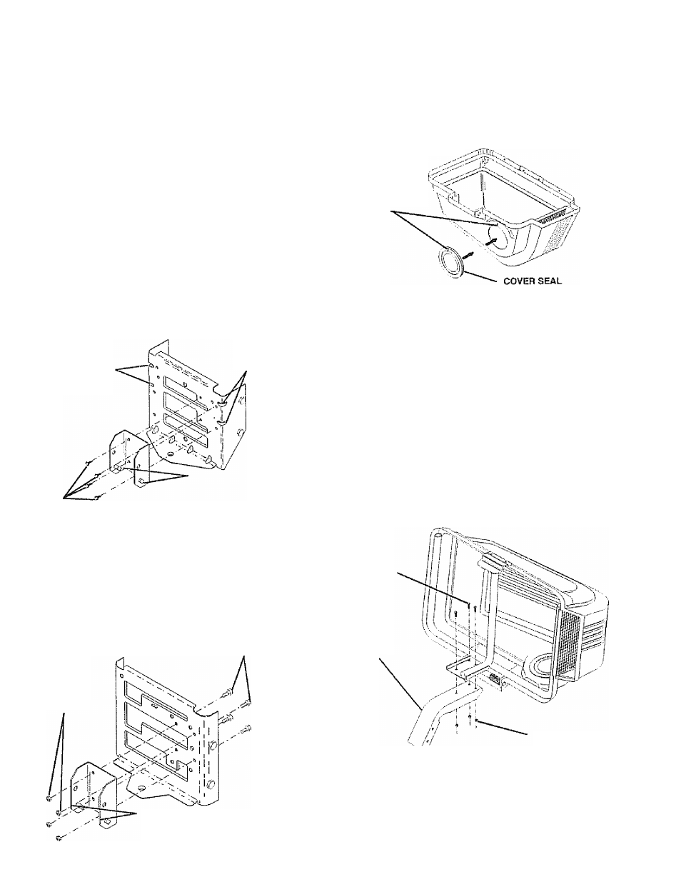
COVER SEAL (See Fig. 3)
No hardware required
" Align mark on seal with mark at cover opening
» Work seal into opening so cover sits between flanges
of seal.
ALIGNMENT
MARKS
Fig. 3
SUPPORT POST (See Fig. 4)
Use Hardware - - GROUP "B"
CAUTION: Containersupport
IS
Spring
loaded and locked to the cover. Handle
cover assembly carefully so as not to
unlatch the cover from the container
support. __________________________
Rotate cover assembly onto its side as shown.
Assemble support post to container support with the
three (3) hex bolts and locknuts. Tighten securely.
HEX BOLTS
SUPPORT
POST
LOCKNUTS
Fig, 4
Fig. 2