Assembly – Sears 536.79751 User Manual
Page 7
Attention! The text in this document has been recognized automatically. To view the original document, you can use the "Original mode".
ASSEMBLY
•
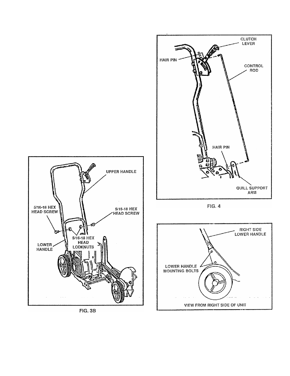
Place the upper handle on the lower handle (See
Fig. 38) and secure in place with two (2) 5/18-18 x
1-1/2 inch hex head screws and two (2) 5/16-18
head head locknuts (found in parts bag)
•
Insert one end of the control rod through the hole in
the clutch lever {See Fig, 4) and attach with a hair
pin (found in the parts bag).
*
Place the clutch lever in the first depth selection and
insert the other end of the control rod through the
hole in the quill support arm (See Fig. 4), Attach with
hairpin (found in parts bag)
*
Move the clutch lever to NEUTRAL position and
latch info position,
NOTE:
It may be necessary to loosen the four screws
and nuts holding the lower handles to the frame (See Fig ,
5). Pry up (forward) on the handles to allow the clutch
lever to freely enter the NEUTRAL position. Retighten
nuts and screws.
FIG. 5