To assemble the edger – Sears 536.79751 User Manual
Page 6
Attention! The text in this document has been recognized automatically. To view the original document, you can use the "Original mode".
CAUTION:
ALWAYS
WEAR
SAFETY
GLASSES OR EYE SHIELDS WHILE
ASSEMBLiNG EDGER.
Figure 1 shows the edger compteteiy assembled.
Reference to the right and left hand side of the edger is
from the operator’s position behind the unit
TO REMOVE EDGER FROM CARTON
® Open the top of the carton
e Remove the packing materia! from the carton
® Remove the plastic parts bag from the carton
® Remove the control rod from the carton,
® Remove the handles from the carton
® Cut down all four corners of the carton
TO ASSEMBLE THE EDGER
® Attach each rear wheel, with the ribs to the outside,
to the edger (See Fig 2) with a 3/8-16 x 1.390 inch
shoulder bolt, spacer and 3/8-16 hex wide flange
lock nut (found in parts bag)
UPPER
HANDLE
CLUTCH LEVER
CONTROL ROD
LOWER
HANDLE
STARTER
HANDLE
BLADE
• Attach the front wheel, with the ribs to the outside,
to the edger (See Fig 2) with a 3/8-16 x 1 390 inch
shoulder bolt and 3/8-16 hex wide flange lock nut
(found in parts bag).
3/0-1 e X 1.3S0 INCH
SHOULDER BOLT
SPACER
(NOT USED ON FRONT WHEEL)
VIEW FROM RIGHT SIDE OF UNIT
FIG. 2
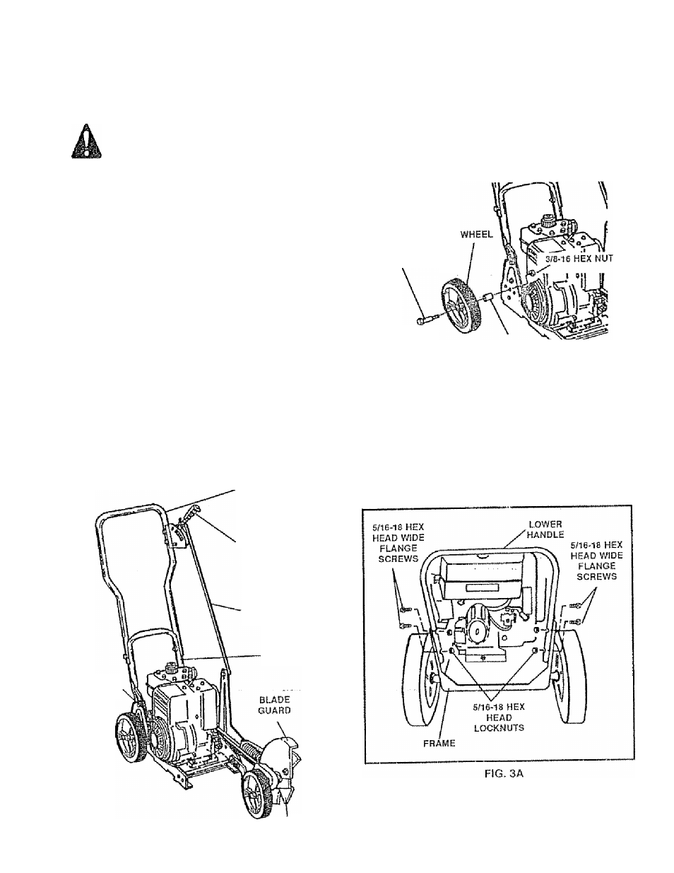
Place the lower handle inside the edger frame (See
Fig. 3A) and secure in place with four (4) 5/16-^
hex head wide flange screws and four (4) 5/"
hex head iocknuts (found in parts bag).
FIG. 1