Jnq instructions, A danger, Danger – Sears Craftsman 919.150270 User Manual
Page 6: Assembly instructions, Installation and startup procedures
Attention! The text in this document has been recognized automatically. To view the original document, you can use the "Original mode".
/li U,, Li. LUUJ i.LvJli“
L/UV ILiJJiUU
%#l^l #"1WI
JNQ INSTRUCTIONS
HU, lOl^i r. i
Tools Needed for Unpacking
A Vz" socket wrwich.
Grasp the handle and lift the air compressor out of the
carton. Remove the styrofoam and plastic brace.
Note the plastic brace attached to the air compres
sor by a h©c screw. Using a
Vz
socket wrench, remove
№e hex screw. Discard both the screw and the plastic
brace.
Tools Needed for Assembly
A
Phillips screwdriver.
Installing rubber feet.
Enclosed with this compressor you will find three
screws, three rubber feet, three eyelets and two flat
washers. You will attech these to the bottom of the unit.
Refer to the air compressor diagram on page 10.
ASSEMBLY INSTRUCTIONS
1. Turn your compressor on its side.
2. Insert eyelet into rubber foot
3. Certter hole in rubber foot over flat washer and hole in
bottom of unit Insert screw and tighten. Note: Longer
screws and flat washers are to be used under front
two feet only. Shorter screw is to be used on back foot
only. Continue this process until all three feet are on
unit
INSTALLATION AND STARTUP PROCEDURES
Location of the Air Compressor
operate the air compressor in a dry, dean, cool and well
v^ilated area. The air intake muffler must
be
kept clear
of obstructions which could reduce air delivery of the air
compressor. The air compressor pump and case are
designed to allow tor proper cooling. Dean or blow off
dust or dirt that coltects on aJr compressor. A clean air
com^essor runs cooler and provides longer service.
Ttte ventilation openings on your air compressor are
necessary to maintain proper operating temperature.
Do not place rags or other containers on or near these
openings.
Extension Cords
Use extra ho^ instead of an extension cord to avoid
voltage drop and power loss to the motor.
if you
must
use an extension txjrd be sure it is:
• a 3-wire extension cord tiiat has a 3-biade grounding
plug, and a 3-slot receptacle that will accept the plug
on the compressor,
• in good coridition.
• 50 feet or shorter.
• 12 gauge (AWG) or larger. (Wire size increase as
gauge number decreases.) 10 AWG and 8 AWG,
may also be used. Do not use 14 or 16 AWG.
Grounding Instructions
W A R N I N G
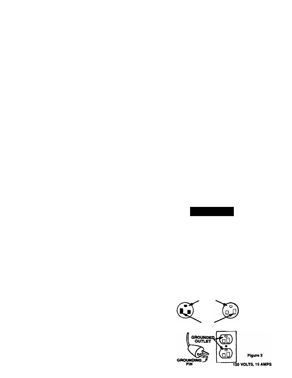
1. The air compressor is designed for 120 volt operation
only and is equipped with a cord hanring a grounding
wire with an appropriate grounding plug. The pltg
must be used with an outlet that has been installed
arto ground^ in accordance with ail local codes and
ordinances (see figure 2). The outlet must have the
same cxjnfiguration as the plug. DO NOT USE AN
ADAPTER.
2. Do not modify the plug that has been provided. If it
does not fit the avallabie outlet, toe correct outlet
should be installed by a qualified etoctrtcian.
3. Before eatto use, ir^pect toe plug and cord. Do not
use if there are signs of damage.
A
DANGER
RISK OF ELECTRICAL SHOCK. IF REPAIR
ING OR REPLACING CORD OR PLUG, THE
GROUNDING WIRE MUST BE KEPT SEPA
RATE
FROM
THE
CURRENT
CARRYING
WIRES. NEVER CONNECT THE GROUND
ING WIRE TO A FLAT BLADE PLUG TER
MINAL.
(THE
GROUNDING
WIRE
HAS
EITHER
GREEN
INSULATION
OR
GREEN
INSULATION WITH A YELLOW STRIPE).
If these grounding irrstojctions are mX completely under
stood, or if in doubt as to wtoetoer tfto comrxessor is
properly grounded, have the installation dtedred by a
qualified electridan.
IMPROPER GROUNDING CAN RESULT IN A
RISK
OF
ELECTRICAL
SHOCK.
IN
THE
EVENT OF A SHORT CIRCUIT, GROUNDING
REDUCES THE RISK OF SHOCK BY PRO
VIDING AN ESCAPE WIRE FOR THE ELEC
TRIC
CURRENT
THIS
AIR
COMPRESSOR
MUST BE PROPERLY GROUNDED. BEAD
THE FOLLOWING.
Plug
Qraund
WMto
'Win
Outlet
6