Compressor pump diagram, Parts list – Sears Craftsman 919.150270 User Manual
Page 11
Attention! The text in this document has been recognized automatically. To view the original document, you can use the "Original mode".
f i i .
¿luuo 1 . 0 irm
U i ' l l b D l O O
IH'J.
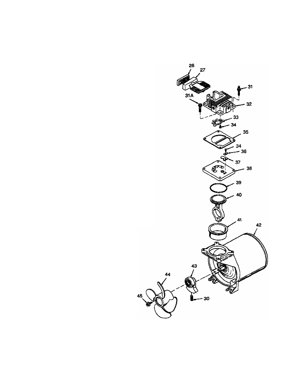
COMPRESSOR PUMP DIAGRAM
HU. lOlii r,
\ L
PARTS LIST
KEY
NO.
PART NUMBER
DESCRIPTION
26
CAC-260-2
Filter
27
CAC-1018
Intake muffler
28
—
Not used
29
—
Not used
30
SSF-2043
Set screw
31
SSF-6637
Shoulder stud y4"-20 x iy,"
31A
SSF-927
(2 used)
Screw y4"-JM X IVe'
<^*^32
CACM234
(2 used)
Head assy.
33
CAC-245-1
Flapper valve Intake
34
SSF9821
Screw #5-40 xy4"
35
CAC-251-2
(3 used)
Gasket
36
CAC-369
Restrictor
37
CAC-246-3
Flapper valve exhaust
*#38
CAC-4203-1
Valve plate assy.
39
SSG-6133
0-ring
40
CAC-4202
Connecting rod assembly
^
41
CAC-249-1
Cylinder sleeve
42
MO-5421
Motor % HP
43
CAC-4201
Eccentric assembly
* 44
CAC-255-1
Fan
45
SSF-3101
Screw #10-24 x%"
NOT ILLUSTRATED
9-16163
9-16271
Si-%-08-2-C
Hose assembly (V4"x 15')
Air chuck
Owners Manual
^ Key 44, can only be purchased
as part of KK-4465 which
Includes (1) SSP-3101 (Key 45).
Key 40,41 can only be
purchased as part of
KK-4464
connecting
rod kit
Key 32, Includes 1 ea. of Key 33 & 34
Key 38, includes 1 ea. of Itey 34, 36 & 37
11