Specification chart, Glx>ssary, General information – Sears Craftsman 919.150270 User Manual
Page 5: Description of operation, Glossary
Attention! The text in this document has been recognized automatically. To view the original document, you can use the "Original mode".
n i I V , . í . i . £ . и и J 1 . J J i 1 1 1
y l i V l b D l O ü 1 1 4 V i ,
KU, lOlíi r. D
SPECIFICATION CHART
Model No.
919.150270
Horsepower
Уд
SCFM @ 40 psig
2.7
SCFM @ 90 psig
го
Displacement CFM
4.0
Bore
2Ув"
Strote
.9"
Vfoltage-Single Phase
110-120
Minimum Branch Circuit Requirement
15 AMPS
Fuse
туре
Tíme Delay
Amperage at Max. Presaire
10.6
•A circuit breaker Is preferred. Use only a fuse or circuit breaker that is the same rating as the branch circuit the air
compressor is operated on. If the air compressor is connected to a circuit protected by fuses, use time delay teses.
GLX>SSARY
SCFM or CFM: Standard Cubic Feet per Minute; a unit
of measurement of air delivery.
PSIG or PSI: Pounds per square inch gauge.
U.L
Listed; Underwriter laboratories; samples of com-
essor outfits, tak№ from production, were submitted to
U.L and found to comply with their requirements for
design and performance.
GENERAL INFORMATION
Congratulations! You have purchased a one cylinder, %
HP compact oilless compressor. The absence of a tank
gives you added mobility as well as ease In storage,
while tt» % HP motor allows you to utilize many air tools,
including inflators, blow guns, spray guns, air brushes,
caulking guns and etchers. Oilless design means you
never have to add oil and its oilless feature also guaran
tees that you will spray entirely oil-free air.
A V#" X15' air hose is supplied wWi your compressor, as
well as an air chuck. Arxessories for use with your r^w
compressor are available through the current Sears
sales catalog, or at full line Sears stores. Your compres
sor will operate many accessories. Check the pressure
and flow rating recommended by tf® access
«7
manu
facturer- be sure it is compatible with the air delivery of
your compressor.
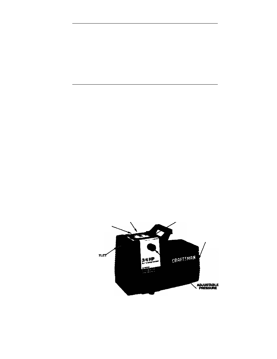
DESCRIPTION OF OPERATION
AIRttHAKE
MUFRieR.
(notsnemm)
AIR
OU
itoAPTESl
MHIN1A!«
RLTER
(not^am/
MR COMPRESSOR
PUMP .
MR COMPRESSOR
HOfDR
Figure 1
Air Compressor Pump; To compress air, the piston
moves up and down in the cylinder. On the downstrcri
air is drawn in through the air intake muffler. The exhaust
valve remains closed. On the upstroke of the piston, air is
compressed. The intake valves close and compressed
air is forced out through the exhaust valve and then
torough the air hose.
VALVE
KNOB
Ad|ustaMe Pressure Valve Knob: The pressure valve
knob controls the amount of pressure going from the air
compressor to tiie accessory. Pressure can be set at any
point between 10 and 100 RS.I. (100 P.S.I. is the highest
pressure this compressor will deliver.) Always set the
pressure valve knob at or below the required pressure for
the accessory being used. THE ADJUSTABLE PRES
SURE VALVE KNOB MUST BE SET AT “START-
BEFORE YOU START THE COMPRESSOR.