To remove mower from carton, How to set-up your lawn mow er, Assembly – Sears 247.370291 User Manual
Page 6
Attention! The text in this document has been recognized automatically. To view the original document, you can use the "Original mode".
ASSEMBLY
NOTE: Reference to right or left hand sidi; of the
mower is observed from the operating pos tion.
Cord
Restraint
TO REMOVE MOWER FROM CARTON
• Remove the carton inserts (if any). Rerrove the
owner’s manual and side discharge chutj which
are in the carton. Lift the mower from the carton, or
cut the corners of the carton and roll the mower
out.
NOTE: A grass catcher bracket is in the bag with the
owner’s manual. Keep this bracket in a safe olace. If
you purchase the optional grass catcher, mi >unt the
bracket on the right side of the upper ha idle as
shown on page 14 of this manual, key 87.
HOW TO SET-UP YOUR LAWN MOW ER
•
Remove any cardboard pieces which nay be
between the upper and lower handles for shipping
purposes.
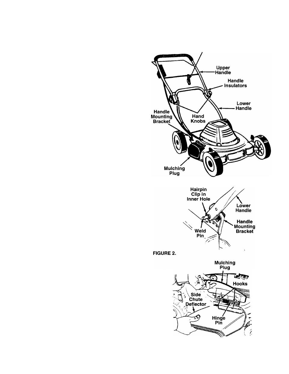
• Pull up and back on the lower handle. P vot the
upper handle up to raise the handle into the operat
ing position. See figure 1.
• The upper handle may be adjusted to three differ
ent height positions. To select desired position,
align one of the three marks on the top of tl e lower
handle insulators with the mark on th( upper
handle insulators. Tighten the hand knobs.
• Remove the hairpin clips from the outer ho e in the
weld pins on the handle mounting bracket;. Place
the hairpin clips in the inner hole. See figun! 2.
NOTE: The outer hole in the weld pin is for storage.
The hairpin clip must be placed in the inner hole for
operation.
•
Make certain all nuts and bolts are tightened
securely.
Your mower has been shipped as a mulcier. To
discharge grass to the side, proceed as follow!;.
• To convert your mower from a mulcher t( a side
discharge mower, lift the mulching plug. See figure
3. Slide the two hooks on the side discharge
deflector under the hinge pin on the mulch ng plug
assembly. Lower the mulching plug.
FIGURE 1.
FIGURE 3.