To stop engine, How to use your chipper-shredoer – Sears Craftman 247.79585 User Manual
Page 9
Attention! The text in this document has been recognized automatically. To view the original document, you can use the "Original mode".
TO STOP ENGINE
• Move throttle control lever to STOP position. See
figure 6.
• Disconnect spark plug \wire and move away from
spark plug to prevent accidental starting while
equipment is unattended. See figure 6.
HOW TO USE YOUR CHIPPER-SHREDOER
Do not attempt to shred or chip any material other
than vegetation found in a normal yard (i.e., branches,
leaves, twigs, etc.).
A
WARNING: THE CHIPPER-SHREDDER
DISCHARGES MATERIALS WITH CON
SIDERABLE VELOCITY. KEEP AWAY
FROM THE AREA AROUND THE CHUTE
DEFLECTOR.
ALWAYS
STOP
THE
ENGINE AND DISCONNECT THE SPARK
PLUG WIRE WHEN REMOVING OR
ATTACHING THE BAG WHEN CHANGING
CONTAINERS OR WHEN REMOVING THE
SHREDDED MATERIAL. WEAR SAFETY
GLASSES AND GLOVES WHENEVER
USING YOUR CHIPPER-SHREDDER.
The chipper-shredder is designed for three different
methods of operation.
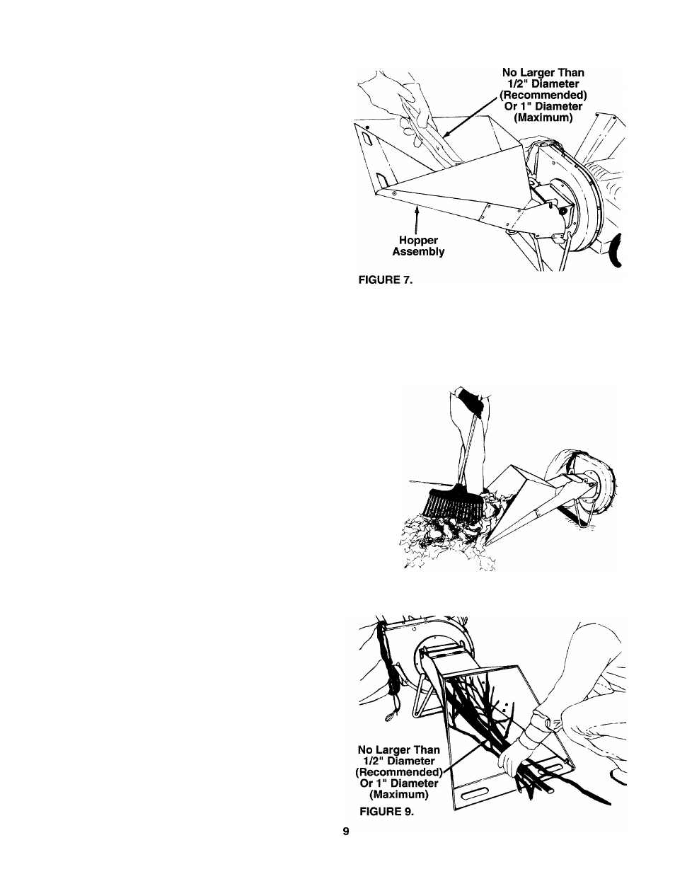
• Leaves and small branches up to 1/2" diameter
(recommended) or 1" diameter (maximum) can be
fed into the hopper assembly when it is in the
raised position. See figure 7. If it becomes neces
sary to push material into the chipper-shredder,
use a small diameter stick—NOT YOUR HANDS.
The stick should be small enough that it will be
ground up if gets into the impeller assembly.
A
WARNING: DO NOT PUT MATERIAL
LARGER THAN 1/2" IN DIAMETER (REC
OMMENDED) or 1" DIAMETER (MAXI
MUM) INTO THE HOPPER ASSEMBLY.
MATERIAL UP TO A MAXIMUM OF 3" IN
DIAMETER MAY BE FED INTO THE
CHIPPER CHUTE. DO NOT ATTEMPT TO
SHRED OR CHIP ANY MATERIAL LARG
ER THAN 3" IN DIAMETER. PERSONAL
INJURY OR DAMAGE TO THE MACHINE
COULD RESULT.
Leaves and small twigs can be raked into the hop
per assembly when the hopper assembly is low
ered to the ground. See figure 8. Small branches
up to 1/2" diameter (recommended) or 1" diam
eter (maximum)
can also be fed into the hopper
assembly in this position. See figure 9.
FIGURE 8.