Control circuit – Carrier 29D User Manual
Page 2
Attention! The text in this document has been recognized automatically. To view the original document, you can use the "Original mode".
f
II0-I-60
CONTROL CIRCUIT
Automatic Operation
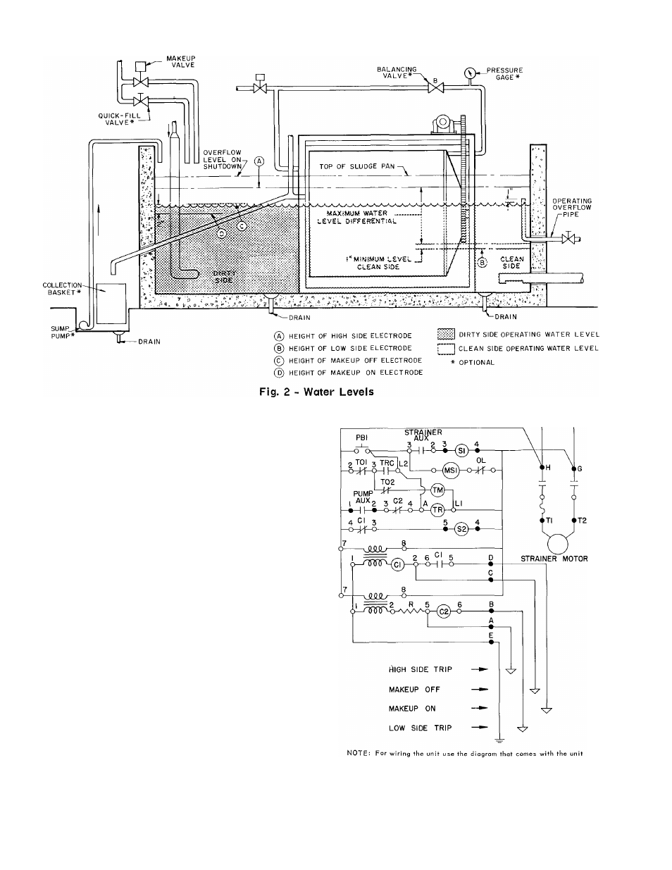
- The water strainer con
trol circuit (Fig. 3) consists of a timer and
level controller. The control circuit is wired thru
an auxiliary contact on the recirculated or chilled
water pump starter. If the fused disconnect switch
is closed, the control circuit is activated when
the pump starts. The strainer is then controlled
automatically by the high or low side electrode.
When either electrode is energized, the control
circuit is completed. This starts the drive motor,
opens the spray water solenoid valve, and trips
the timer.
Normally, as the strainer begins to operate,
the water levels begin to equalize, de-energizing
the electrode. However, the timer contacts remain
closed for the preset timed cycle to maintain
strainer operation. The length of the timed cycle
can be adjusted to suit job requirements. At the
end of the timed cycle, the timer contacts open.
This normally stops the drive motor, and closes
the spray water solenoid valve. However, if the
tank water level is too low, the low side electrode
will maintain the makeup valve open for several
minutes, until the water level rises enough to de
energize the low side electrode.
Manual Operation
- A momentary contact switch
is provided to bypass the automatic tank level con
troller and operate the water strainer for one
timed cycle. This switch permits operation of the
strainer when the water pump is shut down.
Cl
^2
- Relay Coi Is
MSI - Strainer Motor Starter
PB — Push Button
SI - Spray Wtr Solenoid Valve
Fig. 3 - Elementary Control Circuit
S2 - Makeup Wtr Solenoid Valve
TM - Timer Motor
TR — Timer Relay Coil
o
- Terminals on Components
0 — Terminals on Terminal Strip