Indoor blower wheel removal (see fig. 22), Outdoor propeller fan removal (see fig. 23), Outdoor propeller fan removal – Carrier 73Y User Manual
Page 10
Attention! The text in this document has been recognized automatically. To view the original document, you can use the "Original mode".
FAN MOTOR
CLIP (SPRING)
FAN
MOTOR
PARTITION
AIR HANDLING SYSTEM
REMOVAL SCREW
LEFT SIDE SCREW TOP
REAR SIDE
PARTITION SCREW
Fig. 17 — Removing Fan Motor Clip
Fig. 18 — Disengaging Vertical Air Deflector
ROTARY KNOB
CABLE
EXHAUST
DOOR
VENT DOOR
(73YCA213P
AND 243P ONLY)
EXHAUST DOOR
SPRING CLIP
Fig. 20 — Indoor Plastic Scroll Assembly
INDOOR PLASTIC
SCROLL (HIDDEN)
SHEET METAL
PARTITION
CONDENSR
ORIFICE
SCREWS
(2 OUT OF 3)
TYPICAL STRAINER
LOCATION
CONDENSER
COIL
NOTE: Third screw is located on left side of partition as viewed from
front of unit.
Fig. 21 — Screws Securing Partition to indoor
Plastic Scroll Assembly
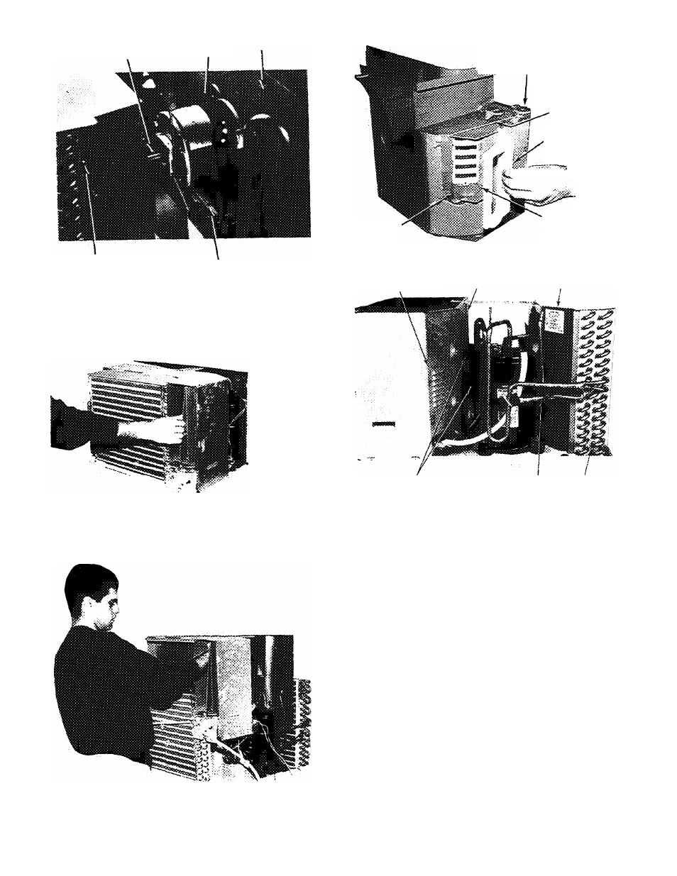
Fig. 19 — Removing Air Handling System
Indoor Blower Wheel Removal (See Fig. 22)
1. Remove chassis from casing. See Chassis Removal in
structions, page 8.
2. Remove air handling system. See Air Handling System
Removal instructions, page 9.
3. Mark shaft at a point where wheel hub and motor shaft
meet to aid in reassembly.
4. Remove spring metal clip from blower wheel hub. See
Fig. 22.
5. Slide off blower wheel from motor shaft.
6. Reverse above procedure for reassembly.
Outdoor Propeller Fan Removal (See Fig. 23)
1. Remove air handling system. See Air Handling System
Removal instructions, page 9.
2. Mark shaft at a point where fan hub and motor shaft
meet to aid in reassembly.
3. Remove spring metal clip from fan hub. See Fig. 23.
4. Remove fan from motor shaft.
5. Reverse above procedure for reassembly.
10