Service – Carrier 38AK007 User Manual
Page 6
Attention! The text in this document has been recognized automatically. To view the original document, you can use the "Original mode".
Unit Preparation
— Make sure that unit has been in
stalled in accordance with installation instructions and ap
plicable codes.
Compressor Mounting
— Compressors are inter
nally spring mounted. Do not loosen or remove compressor
holddown bolts.
Internal Wiring
— Check all electrical connections in
unit control boxes; tighten as required.
Time Guard II® Device
— Time Guard II Circuit pro
vides for a delay of approximately 5 minutes before restart
ing compressor after shutdown from safety device action.
On start-up, the Time Guard timer causes a delay of ap
proximately 15 seconds after thermostat closes.
Refrigerant Service Ports
— Each unit system may
have Schrader type service ports: one on the suction line,
one on the liquid line, and one on the compressor discharge
line. Be sure that caps on the ports are tight.
Cooling
— Set space thermostat to OFF position. Set sys
tem selector switch at COOL position and fan switch at AUTO,
position. Adjust thermostat to a setting below room tem
perature. Compressor starts on closure of contactor.
Check cooling effects at a setting below room tempera
ture. Check unit charge. Refer to Refrigerant Charge sec
tion on page 5.
Reset thermostat at a position above room temperature.
Compressor will shut off.
TO SHUT OFF UNIT - Set system selector switch at OFF
position. Resetting thermostat at a position above room tem
perature shuts unit off temporarily until space temperature
exceeds thermostat setting. Units are equipped with Cycle-
LOC™ protection device. Unit shuts down on any safety
trip and remains off; an indicator light on thermostat comes
on. Check reason for safety trip.
Compressor restart is accomplished by manual reset at
the thermostat by turning the selector switch to OFF posi
tion and then to ON position.
Sequence of Operation
— At start-up, the thermo
stat calls for cooling, and with all safety devices satisfied,
the compressor contactor and fan contactor will energize,
causing the compressor and outdoor-fan motor to operate.
Contacts on TBl terminals 1 and 2 are also energized, al
lowing the field supplied and installed indoor-fan contactor
to function. A field supplied and installed liquid line valve
(connect to TB1 terminals 3 and 4) will also open, allowing
the system to function in cooling. As cooling demand is
satisfied, the thermostat contacts break, deenergizing the
contactor causing the system to shut off. The liquid line
shutoff valve closes minimizing the potential for refrigerant
migration at this time. The compressor does not restart un
til the thermostat again calls for cooling. If a demand for
cooling occurs within 5 minutes after the thermostat is sat
isfied, the system will not restart due to the feature of Time
Guard®II. After the 5 minute time period, the system will
restart as normal upon thermostat demand. The system is
protected with Cycle-Loc device so that the compressor will
not start if a high-pressure or low-pressure fault occurs. Merely
turn down the thermostat to eliminate the cooling demand
to reset the Cycle-Loc device. This should be done only
once, and if system shuts down due to the same fault, de
termine the problem before attempting to reset the Cycle-
Loc device. The 38AK007 unit does not require a crank
case heater.
SERVICE
A CAUTION
When servicing unit, shut off all electrical power to
unit to avoid shock hazard or injury from rotating parts.
Cleaning
— Inspect unit interior at the beginning of each
cooling season and as operating conditions require.
CONDENSER COIL — Inspect coil monthly. Clean con
denser coil annually and as required by location or outdoor-
air conditions.
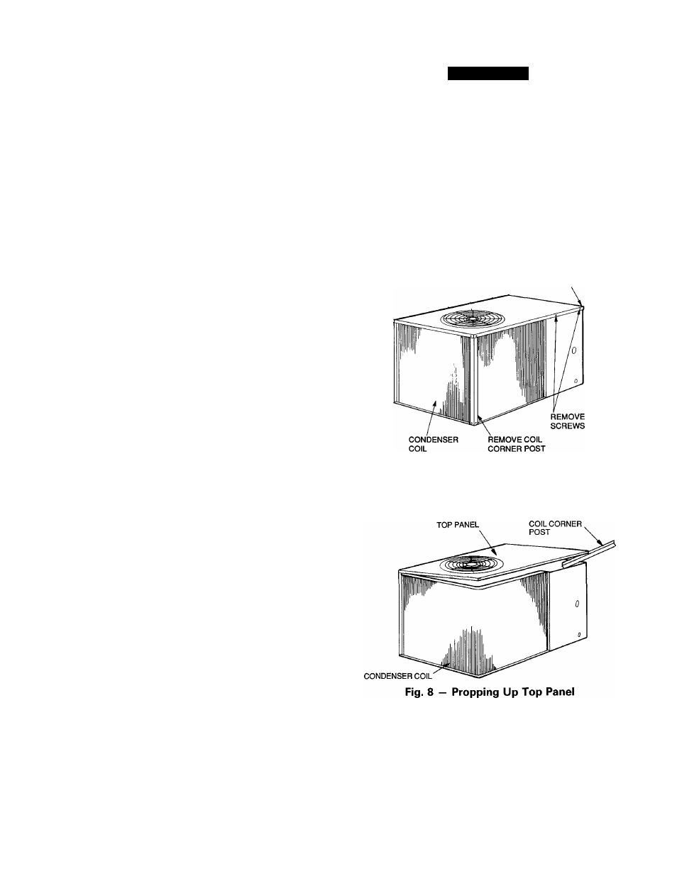
Clean coil as follows:
1. Turn off unit power.
2. Remove top panel screws on condensing unit.
3. Remove condenser coil comer post. See Fig. 7. To hold
top panel open, place coil comer post between top panel
and side panel. See Fig. 8.
CONTROL BOX
CORNER POST
Fig. 7 — Cleaning Condenser Coil