Dimensions (ft-in.), Fig. 1, Front dimensions (ft-in.) – Carrier 38AK007 User Manual
Page 3: Right side fig. 2 - rigging label
Attention! The text in this document has been recognized automatically. To view the original document, you can use the "Original mode".
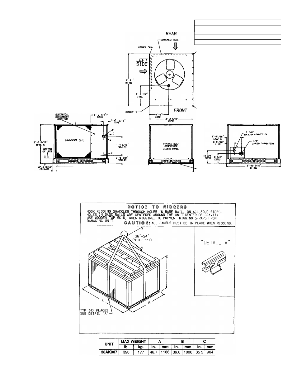
NOTES:
1. Dimensions in
are in miiiimeters.
Center of gravity.
Direction of air fiow.
3
4 Minimum ciearance (locai codes or jurisdiction may
prevaii):
a Bottom to combustibie surfaces 0 in.
b Condenser coil, for proper air flow, 36 in. one side,
12 in the other The side getting the greater ciear
ance is optionai
c Overhead, 60 in to assure proper condenser fan op
eration.
d Between units, controi box side, 42 in per NEC.
e Between unit and ungrounded surfaces, control box
side, 36 in per NEC
f Between unit and block or concrete walls and other
grounded surfaces, control box side, 42 in per NEC
5. With the exception of the clearance for the condenser
coil as stated in notes 5a, b, and c, a removable fence
or barricade requires no clearance
6 Units may be installed on combustible floors made from
wood or class A, B, or C roof covering material
-3’-S 3/IS"
rxp ÍKMSr
► -
0'-2
9/16
LEFT
S I D E
CONNECTION SIZES
A
1%” DIA. [35] FIELD POWER SUPPLY HOLE
B
2” DIA. [51] POWER SUPPLY KNOCK-OUT
c
2V2'’
dia
[64] POWER SUPPLY KNOCK-OUT
D
Ve"
DIA [22] FIELD CONTROL WIRING HOLE
Fig. 1 -
FORIC TRUX SLOTS
<3 SlOeS
ÚM.W
u
3'-3 1/2'-------------------
0003}
FRONT
Dimensions (ft-in.)
0*-2
Ì/4'DJA
Í57J
(TYP 0
PLACES)
RIGHT SIDE
Fig. 2 - Rigging Label