Start-up preliminary checks, Fig. 6 — cooling charging chart — 38ak007, Leak test – Carrier 38AK007 User Manual
Page 5: Evacuate and dehydrate, Refrigerant charge, Chart, Outdoor, Must, Operatin, Liquid
Attention! The text in this document has been recognized automatically. To view the original document, you can use the "Original mode".
FIELD CONTROL WIRING — Install a Carrier-approved
accessory thermostat assembly according to installation in
structions included with the accessory. Locate thermostat
assembly on a solid wall in the conditioned space to sense
average temperature in accordance with thermostat instal
lation instructions.
Route thermostat cable or equivalent single leads of col
ored wire from subbase terminals to low-voltage connec
tions on unit (shown in Fig. 4) as described in Steps 1 through
3 below.
NOTE: For wire runs up to 50 ft, use no. 18 AWG (Amer
ican Wire Gage) insulated wire (35 C minimum). For 50 to
75 ft, use no. 16 AWG insulated wire (35 C minimum).
For over 75 ft, use no. 14 AWG insulated wire (35 C min
imum). All wire larger than no. 18 AWG cannot be directly
connected to the thermostat and will require a junction box
and splice at the thermostat.
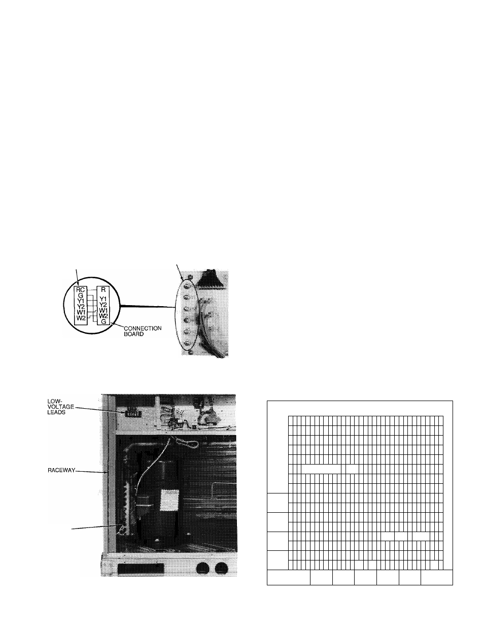
1. Connect thermostat wires to screw terminals of low-
voltage connection board.
2. Pass the control wires through the hole provided in the
comer post.
3. Feed wire through the raceway built into the comer post
to the 24-v barrier located on the left side of the control
box. See Fig. 5. The raceway provides the UL required
clearance
wiring.
THERMOSTAT
between the high- and low-voltage
THERMOSTAT
CONNECTIONS
FOR STANDARD UNIT
WIRING CONNECTIONS
UNIT CONNECTION
BOARD
Fig. 4 — Control Wiring Connections
HOLE IN
END PANEL
(HIDDEN)
START-UP
Preliminary Checks
1. Check that all internal wiring connections are tight and
that all barriers, covers, and panels are in place.
2. Field electrical power source must agree with unit name
plate rating.
3. All service valves must be open.
Leak Test
— Test entire refrigerant system by using soap
bubbles and/or an electronic leak detector.
Evacuate and Dehydrate
— Evacuate and dehy
drate entire refrigerant system by use of the methods de
scribed in GTAC II, Module 4, System Dehydration.
Refrigerant Charge
— Refer to GTAC II, Module 5,
Charging Recovery, Recycling and Reclamation.
Unit panels must be in place when unit is operating dur
ing charging procedure.
Unit is shipped with holding charge only. Weigh in 7 lbs
R-22 to start unit.
NO CHARGE — Use standard evacuating techniques. Af
ter evacuating system, weigh in the specified amount of re
frigerant. (Refer to Table 1.)
LOW CHARGE COOLING - Use Cooling Charging Chart,
Fig. 6. Vary refrigerant until the conditions of the chart are
met. Note the charging chart is different from type nor
mally used. Chart is based on charging the units to the cor
rect subcooling for the various operating conditions. Accu
rate pressure gage and temperature sensing device are required.
Connect the pressure gage to the service port on the liquid
line service valve. Mount the temperature sensing device
on the liquid line, close to the liquid line service valve and
insulate it so that outdoor ambient temperature does not af
fect the reading. Indoor-air cfm must be within the normal
operating range of the unit.
Operate unit and adjust charge to conform with charging
chart, using liquid pressure and temperature to read chart.
TO USE COOLING CHARGING CHART - Initially charge
with 7 lbs. R-22. Place pressure gage at liquid line service
valve. Install thermocouple to liquid line near the liquid line
service valve. Operate unit. Plot liquid pressure and tem
perature on chart and add or reduce charge to meet curve.
Fig. 5 - Field Control Wiring Raceway
CHARGING
CHART
- 38
AK
007
OUTDOOR
FAN
MUST
BE
OPERATIN
0
Q
.
/
g
uj
>
Q
1
AC
Ì
»
1
F AG5^ :
UR№
<
p
< 90-
tt
UJ
1
i
/
7
2
5
o
2
2
/
/
« XX£
:
h
UMe
IF
«
.i
U
ave
/
Ì
s
h
0 r
UOUiO
0
2
PRESSURE
0 25
LIQUID
0
31
VALVE (PS
0 3!
IG
)
i
0 400
Fig. 6 — Cooling Charging Chart — 38AK007