Refrigerant piping sizes, Step 2 - rig and mount the unit, Step 4 — make electrical connections – Carrier 38AK007 User Manual
Page 2: Ik cautlon, A warning
Attention! The text in this document has been recognized automatically. To view the original document, you can use the "Original mode".
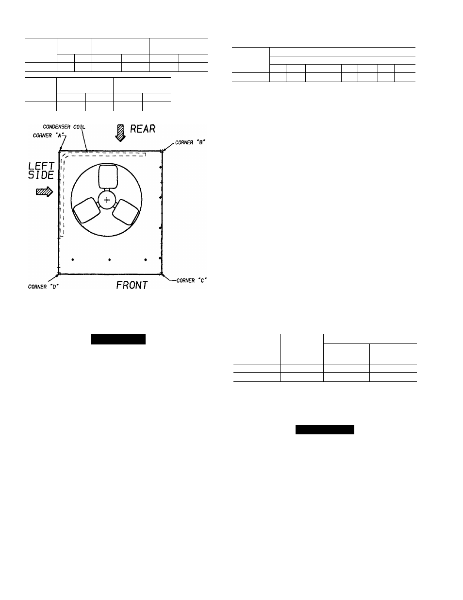
Table 2 — Weight Distribution
REFRIGERANT PIPING SIZES
UNIT
STD. UNIT
WEIGHT
CORNER WEIGHT
(A)
CORNER WEIGHT
(B)
lbs.
kg.
lbs.
kg.
lbs.
kg.
38AK007
340
154
86
39
53
24
UNIT
CORNER WEIGHT
(C)
CORNER WEIGHT
(D)
lbs.
kg.
lbs.
kg.
38AK007
77
35
124
56
Step 2 - Rig and Mount the Unit
ik
CAUtlON
Be sure unit panels are securely in place prior to
rigging.
RIGGING — These units are designed for overhead rig
ging. Refer to rigging label for preferred rigging method.
Spreader bars are not required if top crating is left on unit.
All panels must be in place when rigging. (See Fig. 2) As
further protection for coil faces, plywood sheets may be
placed against sides of unit, behind cables. Run cables to a
central suspension point so that angle from the horizontal is
not less than 45 degrees. Raise and set unit down carefully.
If it is necessary to roll unit into position, mount unit on
rails, using a minimum of 3 rollers.
Apply force to rails,
not unit. If unit is to be skidded into position, place it on a
large pad and drag it by the pad.
Do not apply any force to
unit.
Raise from above to lift unit from rails or pad when unit
is in final position.
After unit is in position, remove all shipping wrapping
and top crating.
Step 3 — Complete Refrigerant Piping Connec
tions
— Suction connection is 1-1/8-in. sweat with plas
tic cap; liquid connection is 1/2-in. sweat with plastic cap.
Follow standard piping practices.
EQUIVALENT LENGTH OF PIPING - FT
COND
UNIT
0-25
26-50
51-75
76-100
Line Size (in. OD)
L
s
L
s
L
s
L
s
38AK007
V2
IVs
V2
IVa
Va
IVe
V2
IVs
L
— Liquid Line
S
— Suction Line
NOTES:
1. Pipe sizes are based on a 2° F loss for liquid and suction lines
2. Pipe sizes are based on an equivalent length equal to the max
imum length of interconnecting piping plus 50 percent for fittings.
3. Charge units with R-22 in accordance with unit installation
instructions.
SIZE REFRIGERANT LINES - Consider length of pip
ing required between condensing unit and evaporator, amount
of liquid lift, and compressor oil return. See Table 3 and
also refer to Part 3 of Carrier System Design Manual for
design details and line sizing. Refer to evaporator installa
tion instructions for additional information.
INSTALL FILTER DRIER AND MOISTURE INDICA
TOR — The filter drier is factory supplied and field in
stalled. Moisture indicator is a field-installed option and should
be installed just after liquid line shutoff valve.
Do not use a
receiver; there is none provided with unit and one should
not be used.
NOTE: Unit is shipped with R-22 holding charge. System
pressure must be relieved before removing caps.
Pass nitrogen or other inert gas through piping while braz
ing to prevent formation of copper oxide.
Install field-supplied thermostatic expansion valve to evap
orator section. It is recommended that a field supplied liq
uid line solenoid be positioned in the main liquid line close
to the evaporator coil, and wired to close when compressor
stops to minimize refrigerant migration during the “OFF”
cycle.
Table 3 — Liquid Line Data
UNIT 38AK007
MAX
ALLOWABLE
LIQUID
LIFT (ft)
LIQUID LINE
Max Allowable
Pressure Drop
(psi)
Max Allowable
Temp Loss
(F)
60 Hz
86
7
2
50 Hz
72
7
2
NOTE: Values shown are for units operating at 45 F saturated suc
tion and 95 F entering air
Step 4 — Make Electrical Connections
A WARNING
Unit cabinet must have an uninterrupted, unbroken elec
trical ground to minimize the possibility of personal in
jury if an electrical fault should occur. This ground may
consist of electrical wire connected to unit ground lug
in control compartment, or conduit approved for elec
trical ground when installed in accordance with NEC
ANSI (American National Standards Institute)/NFPA
(National Fire Protection Association) 70-1987 and lo
cal electrical codes. Failure to follow this warning could
result in the installer being liable for personal injury of
others.