A warning, Ik caution, Fig. 7—typical circuit connections – Carrier 38QRA User Manual
Page 5
Attention! The text in this document has been recognized automatically. To view the original document, you can use the "Original mode".
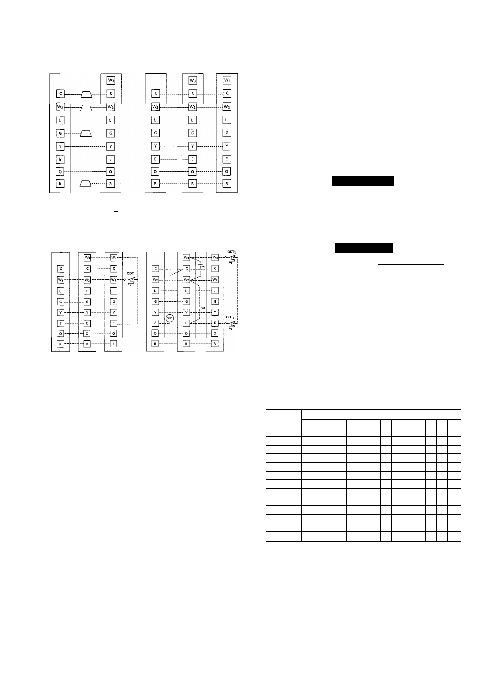
SYSTEMS WITHOUT OUTDOOR THERMOSTATS
Thermostat Indoor
Outdoor
Subbase
^
. ,
Splice
Terminal
Connection Board
Thermostat
Subbase
Terminal
Board
Terminal
Board
D VWTH FF1A, 40nc FAN COIL
USED WITH FD3A, FB4A. FB5A. FK4A,
40AQ, 40DQ, 40QBAÎH OR 40YAWYZ
!
V FIELO SPLICE
SYSTEMS WITH ONE OUTDOOR THERMOSTAT
Thermostat
Indoor
Subbase
Terminal
Board
A88285
SYSTEMS WITH TWO OUTDOOR THERMOSTATS
USED WITH {?1A. 4QRC FAN COIL
- FACTOflVVVIRlNG
■ FIEIOWIRING
OU'BOORTHERMOSTAT
SUPPIEUENTAI. HEAT RELAV
REMOVE FAaORYINSTAUEO JUMPERS ON INDOOR FAN COIL TERMINAL BOARD WHEN INSTALUNSOUTDOORTHERMOSTATS
Fig. 7—Typical Circuit Connections
A88286
Cooling
On a “call for cooling”, the thermostat “makes” circuits R- O,
R-Y and R-G. Circuit R-0 energizes the reversing valve, switching
it to cooling position. Circuit R-Y energizes the contactor, starting
outdoor fan motor and compressor circuit. R-G energizes the
indoor unit blower relay, starting the indoor blower motor on high
speed.
When the thermostat is satisfied, its contacts open, de-energizing
the contactor and blower relay. Compressor and motors should
stop.
Heating
On a “call for heating”, the thermostat “makes’ ’ circuits R- Y and
R-G. Circuit R-Y energizes contactor, starting outdoor fan motor
and compressor. Circuit R-G energizes the indoor blower relay,
starting the blower motor on high speed.
Should the temperature continue to fall, R-W2 is made through the
second-stage room thermostat bulb. Circuit R-W2 energizes a
sequencer, bringing on the first bank of supplemental electric heat
and providing electrical potential to the second heater sequencer (if
used). If the outdoor temperature falls below the setting of the
outdoor thermostat, (field-installed operation) the contacts close to
complete the circuit and bring on the second bank of supplemental
electric heat.
When the thermostat is satisfied, its contacts open, de-energizing
the contactor and sequencer. All heaters and motors should stop.
Defrost
The defrost control is a time/temperature control which includes a
field-selectable time period between defrost cycles (30, 50 and 90
minutes, factory set at 90 minutes). Quick connects are located at
board edge.
The electronic timer and the defrost cycle will start only when the
contactor is energized, defrost thermostat is closed and the timing
device has completed one cycle.
The defrost mode is identical to the cooling mode except that the
outdoor fan motor stops and second stage heat is turned on to
continue warming the conditioned space.
A WARNING
Service valve gage ports are not equipped with Schrader
valves. To prevent personal injury, make sure gage manifold
is connected to the valve gage ports before moving valves off
fully back seated position. Wear safety glasses and gloves
when handling refrigerant.
ik CAUTION
Compressor damage may occur if system is overcharged. |
Step 9—Refrigerant Charging
NOTE: See Table 2 for correct system charge of tested combi
nation.
Cooling
To check and adjust charge during cooling season, use Tables 4
and 5 and the following procedure:
1. Operate unit a minimum of 15 minutes before checking
charge.
2. Measure suction pressure by attaching a gage to suction valve
service port.
Table 4—Superheat Charging Table
(Superheat Entering Suction Service Valve)
OUTDOOR
INDOOR COIL ENTERING AIR (F) WB
TEMP
50
52
54
56
58
60
62
64
66
68
70
72
74
76
55
9
12
14
17
20
23
26
29
32
35
37
40
42
45
60
7
10
12
15
18
21
24
27
30
33
35
38
40
43
65
—
6
10
13
16
19
21
24
27
30
33
36
38
41
70
_
7
10
13
16
19
21
24
27
30
33
36
39
75
—
—
6
9
12
15
18
21
24
28
31
34
37
80
—
—
—
—
5
8
12
15
18
21
25
28
31
35
85
8
11
15
19
22
26
30
33
90
5
9
13
16
20
24
27
31
95
6
10
14
18
22
25
29
100
8
12
15
20
23
27
105
5
9
13
17
22
26
110
6
11
15
20
25
115
8
14
18
23
—Do not attempt to charge system under these conditions or refrigerant
slugging may occur.
3. Measure suction line temperature by attaching a service
thermometer to unit suction line near suction valve. Insulate
thermometer for accurate readings.
4. Measure outdoor coil inlet air dry-bulb temperature with a
second thermometer.
5. Measure indoor coil inlet air wet-bulb temperature with a sling
psychrometer.