Type a, Type b, Fig. 5—accurater® (bypass type component) – Carrier 38QRA User Manual
Page 4: Step 6—make electrical connections, Step 7—install electrical accessories, Step 8—start-up, A warning
Attention! The text in this document has been recognized automatically. To view the original document, you can use the "Original mode".
NOTE: Unit is shipped with R-22 factory holding charge indi
cated on unit rating plate.
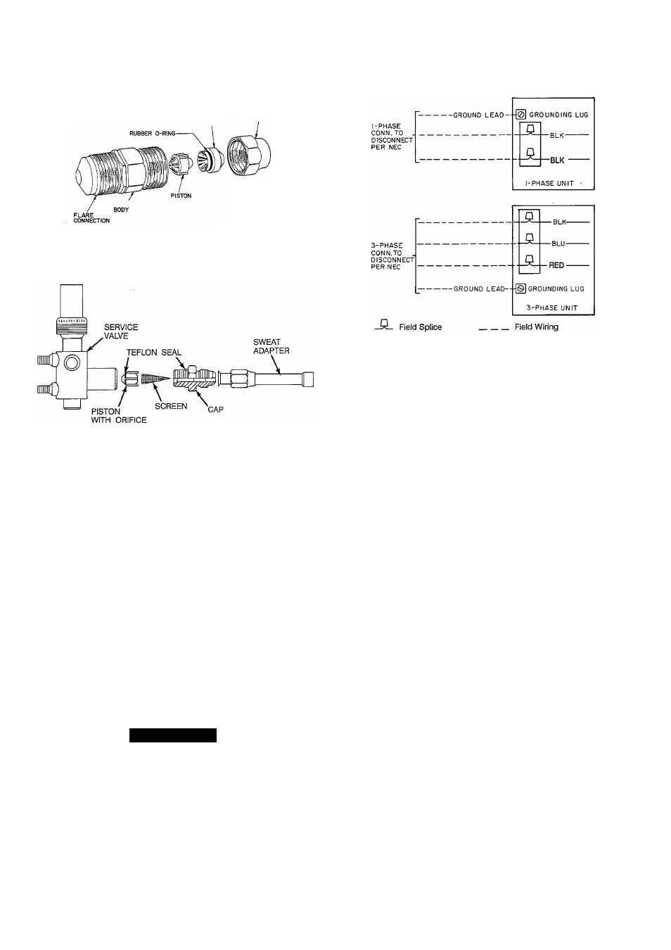
TYPE A
A90287
TYPE B
A90300
Fig. 5—AccuRater® (Bypass Type Component)
Step 6—Make Electrical Connections
Be sure field wiring complies with local and national fire, safety
and electrical codes, and voltage to system is within limits shown
on unit rating plate. Contact local power company for correction of
improper voltage. See unit rating plate for recommended circuit
protection device and minimum circuit amps for wire size.
NOTE: Operation of unit on improper line voltage constitutes
abuse and could affect unit reliability. See unit rating plate. Do not
install unit in system where voltage may fluctuate above or below
permissible limits.
NOTE: Use copper wire only between disconnect switch and
unit.
BRANCH CIRCUIT DISCONNECT - Install branch circuit dis
connect per NEC of adequate size to handle unit starting current.
Locate disconnect within sight from and readily accessible from
unit, per Section 440-14 of NEC.
A WARNING
According to NEC, ANSI/NFPA 70, and local codes, the
cabinet must have an uninterrupted or unbroken ground, to
minimize personal injury if an electrical fault should occur.
The ground may consist of electrical wire or metal conduit
when installed in accordance with existing electrical codes.
Failure to follow this warning could result in an electric
shock, fire, or death.
GROUND AND POWER WIRES — Route power wires through
opening in unit side panel and connect in unit control box as shown
on unit wiring label and Fig. 6. Unit must be grounded.
Factory Wiring
Fig. 6—Line Power Connections
A91315
CONTROL CIRCUIT WIRING - Control voltage is 24 volts (40
va minimum). See Fig.. 7 and unit wiring label for field-supplied
wiring details. Route control wires through opening in unit side
panel to connection in unit control box. Use furnace or fan coil
transformer as 24 volt (40 va minimum) supply for system or use
accessory transformer.
NOTE: Use No. 18 AWG color-coded, insulated (35 C mini
mum) wires. If thermostat is located more than 100 ft from unit (as
measured along the control voltage wires), use No. 16 AWG
color-coded wires to avoid excessive voltage drop.
NOTE: The defrost timer is factory set for 90-minute cycles. The
timer can be field set for 30- and 50-minute cycles depending on
defrost conditions in your geographical location.
Step 7—Install Electrical Accessories
Refer to the individual instructions packaged with kits or acces
sories when installing.
See your local distributor or dealer for specific component
information.
Step 8—Start-Up
1. When equipped with a crankcase heater, energize crankcase
heater a minimum of 24 hours before starting unit. To energize
heater only, set thermostat at OFF position and close electrical
disconnect to outdoor unit.
2. Fully back seat (open) liquid- and vapor-tube service valves.
3. Unit is shipped with valve stem(s) front seated and caps
installed. Replace stem caps after system is opened to refrig
erant flow (back seated). Replace caps finger tight plus
1/6-tum.
4. Close electrical disconnects to energize system.
5. Set room thermostat at desired temperature.
6. Set room thermostat at HEAT or COOL and fan switch at ON
or AUTO, as desired. Operate unit for 15 minutes.
SEQUENCE OF OPERATION — With power supplied to indoor
and outdoor units, transformer and crankcase heater are energized.