Fig. 5—fresh air duct for tightly sealed buildings – Carrier 61SW User Manual
Page 4
Attention! The text in this document has been recognized automatically. To view the original document, you can use the "Original mode".
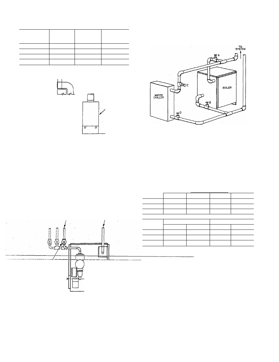
Table 3—Fresh Air Duct Capacities for Tightly
Sealed Houses*
FRESH AIR
DUCT SIZE
(IN.)
1/4-MESH
SCREEN
(BTUH)
WOOD
LOUVERS
(BTUH)
METAL
LOUVERS
(BTUH)
3 X 12
144,000
36,000
108,000
8x8
256,000
64,000
192,000
8
X
12
384,000
96,000
288,000
8-1/2
X
16
512,000
128,000
384,000
exposed to refrigerated air circulation, the boiler piping system
must be equipped with flow control valves or other automatic
means to prevent gravity circulation of the boiler water during the
cooling cycle.
‘Based on opening mesh soreen, or metal louvers.
FRESH
^AIR
DUCT
FRESH AIR DUCT
FOR TIGHTLY
SEALED HOUSE
BOILER
A90065
Fig. 5—Fresh Air Duct for Tightly Sealed Buildings
side. (See Fig. 6.) Any other piping method will short-circuit water
flow through the boiler and insufficient heat will result from the
premature limit control cutout. When a boiler is installed on an
oversized piping system (a typical example is replacement of a
gravity boiler with a forced circulation boiler) and piping or
radiation are not changed, an adjustable flow control valve or
square head cock must be added to reduce the water flow through
the boiler. This allows proper water temperature (160° F mini
mum) to be obtained which eliminates continuous condensate on
the sections. If more than 1 return is used, use a flow control valve
or square head cock in each return. (See Fig. 6.)
A84191
Fig. 7—Piping With Refrigeration System
Step 5—Gas Piping
The gas supply line should be a separate line directly from the
meter to the boiler, if possible. Refer to Table 4 for the recom
mended gas pipe sizing. Do not use cast-iron or galvanized pipe.
For additional information, refer to “National Fuel Gas Code”
NFPA No. 54-1988/ANSI Z223.1-1988.
Table 4-Gas Pipe/Tubing Capacity
NATURAL GAS
Iron Pipe—Btuh Input
RETURN
SUPPLY
FLOW CONTROL VALVE
OR
SQUARE HEAD COCK
(Ft)*
1/2 in.
3/4 in.
1 in.
1-1/4 in.
20
92,000
190,000
350,000
625,000
40
63,000
130,000
245,000
445,000
60
50,000
105,000
195,000
365,000
PROPANE GAS
Length
Copper Tubing—OD
Iron Pipe
(Ft)*
5/8 in.
3/4 in.
-1/2 in.
3/4 in.
20
131,000
216,000
189,000
393,000
40 .
90,000
145,000
129,000
267,000
60
72,000
121,000
103,000
217,000
‘The length of pipe or tubing should be measured from the gas meter or
propane second stage regulator.
"liTOidTow spbfriiTlohgTTihTbf piperld's'best to'^slope all pipeTiyA--
in. every 15 ft to prevent traps. All horizontal runs should slope
away from the meter to risers. Risers should be used to connect to
the boiler and to the meter.
A84190
Fig. 6—System Water Line Connection
Step 4—Boiler With Refrigeration System
When a water boiler is used in connection with a chilled-water
system, it must be installed so that the chilled medium is piped in
parallel with the heating boiler with appropriate valves to prevent
the chilled medium from entering the heating boiler. An example
of such piping is shown in Fig. 7. When the boiler is connected to
heating coils located in air handling units where they may be
Joint compounds (pipe dope) should be applied sparingly and only
to the male threads of the joints. Consult your local supplier for the
-type-of-compound-to.-berusedzThisTpipe-dQp.ermusl-be-resistant-to-
the action of propane gas.
Install a sediment trap in the riser leading to the boiler. This
sediment trap will serve as a trap for dirt or condensate. This
sediment trap can be installed by connecting a tee to the riser
leading to the boiler, so that the straight-through section of the tee
is vertical. Then, connect a capped nipple into the lower end of the
tee. The capped nipple should extend below the level of the gas
controls. (See Fig. 8.)
When a gum filter is required by local codes, install it in
accordance with their requirements.