A warning, Table 2—dimensions (in.), Warning – Carrier 61SW User Manual
Page 2
Attention! The text in this document has been recognized automatically. To view the original document, you can use the "Original mode".
A85084
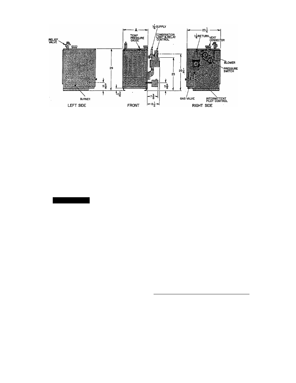
Fig. 2—Dimensional Drawing
2. Combustible floors-Do not install the boiler on carpeting.
When the boiler is installed on a combustible floor, you must
use a factory-supplied combustible floor installation kit con
taining a rectangular piece of insulation material. Position the
insulation on the combustible floor and place the boiler on top
of the insulation.
3. Alcove installation only — Maintain at least 6 in. from com
bustible material on the left-hand (LH) side, 6 in. from the
back and 6 in. from the top.
4. Leave enough room for service access on the right-hand (RH)
side and front. A minimum of 24 in. is required.
A
WARNING
The boiler, when installed, must be electrically grounded in
accordance with the National Electrical Code, ANSI/NFPA
No. 70-1988.
Step 2—Air For Combustion and Ventilation
Table 2—Dimensions (In.)
MODEL
AND SIZE
61SW-042100
61SW-075100
61SW-112100
-etsw^rsoioo”
61SW-187100
61SW-225100
11
14-1/4.
17-1/2
■'20-3/4“
24
27-1/4
VENT
CONNECTION
4*
4*
4*
■ 4*~
*With factory-supplied adaptor installed.
The relief-air supply must be in the same atmospheric pressure
zone as the combustion-air inlet supply to the boiler.
^^1 gas-fired equipment must'be'supplied^witlrthe airthat enters’
into the combustion process and is then vented to the outdoors.
Sufficient air must enter the boiler room to replace that air drawn
up the vent stack. Replacement air must be provided by means of
ducts from the outside to the boiler location or conditioned space.
Under all conditions, enough air must be provided to insure there
will not be a negative pressure condition within the boiler room or
space.
In the past, the infiltration of outside air assumed in heat loss
calculations (1 air change per hour) was assumed to be sufficient.
However, current construction methods using more insulation and
WA
vapor barriers, tighter fitting and gasketed doors and windows or
weather-stripping, and mechanical exhaust fans now require the
positive introduction of outside air.
The requirements for combustion and ventilation air depend upon
whether the boiler is located in a confined or unconfined space.
An unconfined space is defined as a space whose volume is not
less than 50 cu ft per 1000 Btuh of the total gas input rating of all
appliances installed in that space.
Advise the owner of the necessity for keeping air passages to the
boiler area free of obstructions. This clearance is necessary so
combustion air can enter freely into the combustion chamber. It is
also necessary to provide adequate ventilating air.
EQUIPMENT LOCATED IN CONFINED SPACES
1. All Air From Inside Building
The confined space shall be provided with 2 permanent
openings communicating directly with an additional room(s)
of sufficient volume so that the combined volume of-all spaces
meets the criteria for an confined space. The total input of all
gas utilization equipment in the confined space shall be
considered in making this determination. Each opening shall
have a minimum free area of 1 square in. per 1000 Btuh of the
total input rating of all gas utilization equipment in the
confined space, but not less than 100 square in. One opening
shall be within 12 in. of the top and 1 within 12 in. of the
bottom of the enclosure. (See Fig. 3.)
—2wUl-Air-FTom-Outdoors-------------------------- ^---------------------------
The confined space shall be provided with 2 permanent
openings, 1 within 12 in. of the top and 1 within 12 in. of the
bottom of the enclosure. The openings shall communicate
directly, or by ducts, with the outdoors or spaces (crawl of
attic) that freely communicate with the outdoors.
a. When directly communicating with the outdoors, each
-^^opening^shall-have-a-minimumTreerareamf-l-square-in-per=
4000 Btuh of total input rating of all equipment in the
enclosure. (See Fig. 4.) Use F and G.
b. When communicating with the outdoors with vertical
ducts, each opening shall have a minimum free area of 1
square in. per 4000 Btuh of total input rating of all
equipment within the enclosure. (See Fig. 4.) Use D and E.
c. When communicating with the outdoors with vertical
ducts, each opening shall have a minimum free area of 1
square in. per 2000 Btuh of total input rating of all
equipment in the enclosure. (See Fig. 4.) Use A and B or A
and C.