K caution, Step 5—make electrical connections, Disconnect per n. e. c. and/ or local codes – Carrier 38TMA User Manual
Page 3: Contactor, Fig. a—line power connections, A warning, Caution, Line power connections, Warning
Attention! The text in this document has been recognized automatically. To view the original document, you can use the "Original mode".
Run refrigerant tubes as directly as possible, avoiding unnecessary
turns and bends. Suspend refrigerant tubes so they do not damage
insulation on vapor tube and do not transmit vibration to structure.
Also, when passing refrigerant tubes through wall, seal opening so
vibration is not transmitted to structure. Leave slack in refrigerant
tubes between structure and unit to absorb vibration.
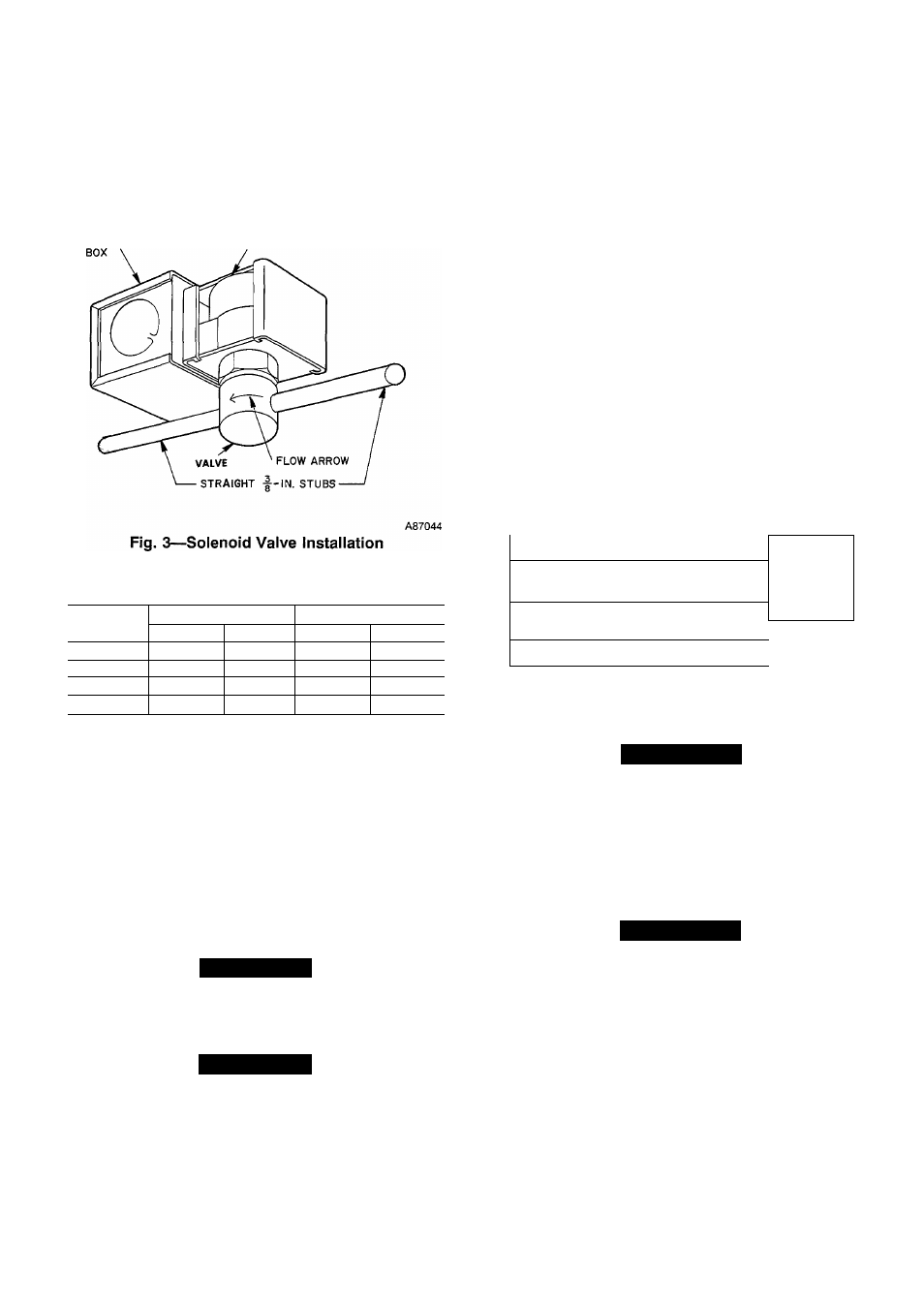
ELECTRICAL JUNCTION
ELECTRIC COIL
Table 1—Refrigerant Connections and
Recommended Liquid and Vapor Tube Diameters
UNIT SIZE
LIQUID
VAPOR
Conn. Dia.
Tube Dia.
Conn. Dia.
Tube Dia.
024
3/8
3/8
5/8
5/8
030, 036
3/8
3/8
3/4
3/4
042, 048
3/8
3/8
7/8
7/8
060
3/8
3/8
7/8
1-1/8
1. Tube diameters are for lengths up to 50 ft. For tube sets over 50 ft. consult
Long-Line Application Guideline.
2. Do not apply cap-tube indoor coils to these units.
OUTDOOR UNITS CONNECTED TO FACTORY-APPROVED
INDOOR UNITS
Outdoor units contain correct system refrigerant charge for oper
ation with indoor unit of the same size when connected by 25 ft
(7.62m) of field-supplied or factory accessory tubing. Check
refrigerant charge for maximum efficiency (see Refrigerant Charg
ing).
REFRIGERANT TUBING
Connect tubing to fittings on outdoor unit vapor and liquid service
valves. (See Fig. 2.)
£k
CAUTION
A brazing shield MUST be used when tubing sets are being
brazed to the service valves to prevent damage to the painted
unit surface.
A
CAUTION
To avoid valve damage while brazing, service valves must be
wrapped with a heat-sinking material such as a wet cloth.
SWEAT CONNECTION
Use refrigerant grade tubing. Service valves are closed from
factory and ready for brazing. After wrapping the service valve
with a wet cloth, the tubing set can be brazed to the service valve
using either silver bearing or non-silver bearing brazing material.
Consult local code requirements. Refrigerant tubing and indoor
coil are now ready for leak testing. This check should include all
field and factory joints.
Step 5—Make Electrical Connections
Be sure field wiring complies with local and national fire, safety
and electrical codes, and voltage to system is within limits shown
on unit rating plate. Contact local power company for correction of
improper voltage. See unit rating plate for recommended circuit
protection device.
NOTE:
Operation of unit on improper line voltage constitute?
abuse and could affect unit reliability. See unit rating plate. Do not
install unit in system where voltage or phase imbalance may
fluctuate above or below permissible limits.
NOTE;
Use copper wire only between disconnect switch and
unit.
DISCONNECT
PER N. E. C. AND/ OR
LOCAL CODES
CONTACTOR
FIELD POWER
o°o
OoO
WIRING
FIELD GROUND ^
D
WIRING 1 GROUN
A91056
LUG
Fig.
A
—Line Power Connections
A
WARNING
To avoid personal injury or death, do not supply power to unit
with compressor terminal box cover removed.
BRANCH CIRCUIT DISCONNECT
Disconnect must be of adequate size to handle unit starting cunent,
but not larger than maximum fuse size shown on unit rating plate.
Locate disconnect within sight from and ready accessible from
unit, per Section 440-14 of NEC.
A
WARNING
According to NEC, ANSI/NFPA 70, and local codes, the
cabinet must have an uninterrupted or unbroken ground, to
minimize personal injury if an electrical fault should occur.
The ground may consist of electrical wire or metal conduit
when installed in accordance with existing electrical codes.
Failure to follow this warning could result in an electric
shock, fire, or death.
ROUTE GROUND AND POWER WIRES
Remove access panel and control box cover to gain access to unit
wiring. Extend wires from disconnect through power wiring hole
provided (see Fig. 2) and into unit control box. Size wires per
NEC, but not smaller than minimum wire size shown on unit rating
plate.