A caution, Step 4—make piping connections – Carrier 38TMA User Manual
Page 2
Attention! The text in this document has been recognized automatically. To view the original document, you can use the "Original mode".
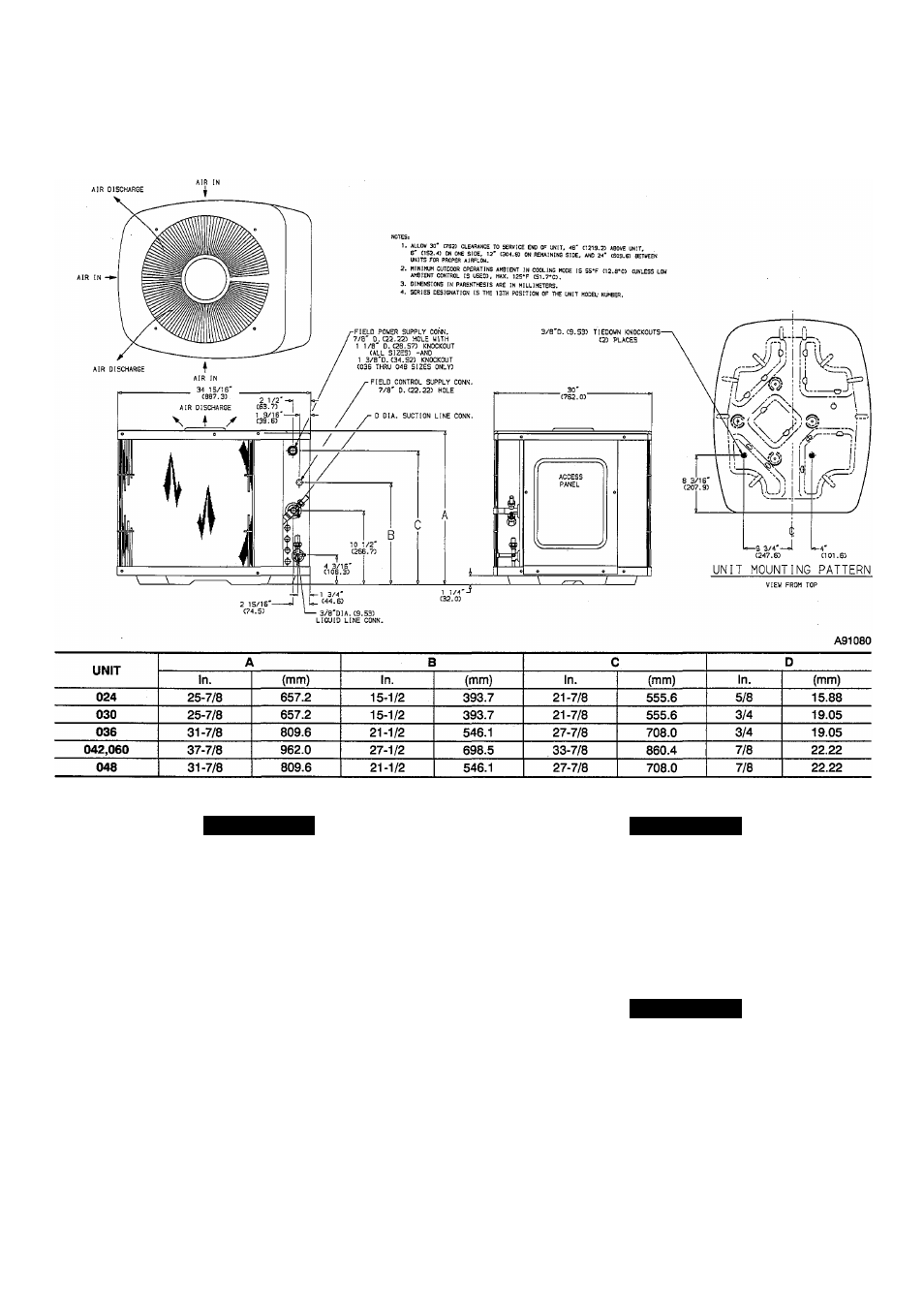
Fig. 2—Unit Reference Drawing
A CAUTION
A CAUTION
If unit is to be installed on system with a thermostatic
expansion valve (TXV), removal of the indoor coU piston is
required.
Step 4—Make Piping Connections
Outdoor units may be connected to indoor sections using accessory
tubing package or field-supplied tubing of refrigerant grade,
correct size, and condition. The liquid- and vapor-tube diameters
can be determined by using Table 1. For tubing requirements
beyond 50 ft (15.24m), obtain information from your local
distributor.
If required, install solenoid valve in liquid line to achieve desired
rating. (See Fig. 3.)
DO NOT BURY MORE THAN 36 IN. (914mm) OF RE
FRIGERANT TUBING IN GROUND. If any section of
tubing is buried, there must be a 6- in.(152mm) vertical rise
to the valve connections on the outdoor unit. K more than the
recommended length is buried, refrigerant may migrate to
cooler buried section during extended periods of unit shut
down, causing refrigerant slugging and possible compressor
damage at start-up.
A CAUTION
For systems installed with a liquid-hue solenoid valve,
solenoid valve must be energized during evacuation and
purging for effective evacuation.
If either refrigerant tubing or indoor coil is exposed to atmospheric
conditions for longer than 5 minutes, it must be evacuated to 1000
microns to eliminate contamination and moisture in the system.