Optimizer coimtrou^a^llatioisi, System wiring data (24 v), Optimizer control settings – Carrier 38CQ User Manual
Page 2
Attention! The text in this document has been recognized automatically. To view the original document, you can use the "Original mode".
OPTIMIZER COIMTROU^a^LLATIOISI
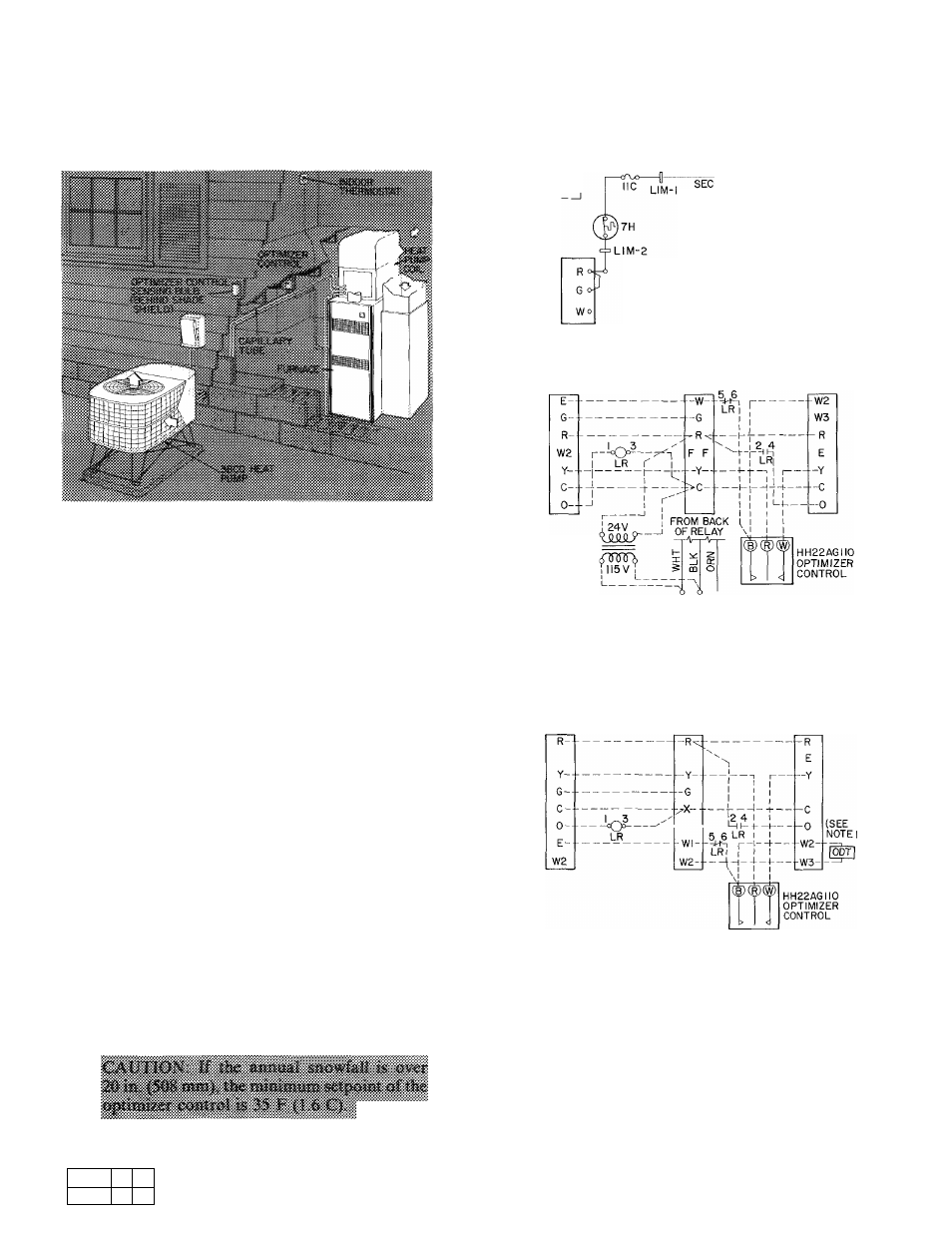
A 5-ft (1.5 m) capillary tube connects the outdoor
temperature sensing bulb to Optimizer body. Locate
bulb outdoors behind the shade shield. Mount
Optimizer indoors for easy accessibility, Fig. 2.
Fig. 2 — Typical Optimizer Installation
System Wiring Data (24 v)
1. Connect Optimizer system control wiring, Fig. 3.
2. Furnace transformer supplies 24-v power for
system.
3. Required indoor fan relay is energized thru ter
minal G, Fig. 3.
4. Electric furnace terminals R and C must be
powered by transformer 24-v secondary; if not,
change wiring.
5. For example of complete Optimizer system
diagram, refer to heat pump wiring book.
Optimizer Control Settings
^1. Set Optimizer temperature dial to transfer heat
ing function to furnace at a temperature equal
to the calculated balance point plus the control
differential setting (factory set at 10 F [-12.2 C]).
Balance point is usually 30 F (-1.1 C) to 35 F
(1.6 C). Calculation sheets are available from
Carrier. Minimum setting is 20 F (-6.7 C).
2. Factory differential setting is 10 F (-12.2 C).
In areas of less than 20 in. (508 mm) annual snow
fall, setting can be readjusted to 5 F (-15 C).
Remove Optimizer cover for access to differ
ential adjustment wheel.
I
I r ~
L2^LI
LINE-1
LINE-2
1
]
I I________
I
I
I_______
IA "SEC-2
OPTIMIZER SYSTEM-38 SERIES HEAT
PUMP/58SE OR 58GS GAS FURNACE;
COOLING, HEATING, EMERGENCY
HEAT
THERMOSTAT TERMINALS
38CQ900-Ill
(MAN CHANGEOVER)
38CQ900-08I
(AUTO CHANGEOVER)
58H SERIES
OIL FURNACE
PRIMARY RELAY
TERMINALS
HEAT PUMP
TERMINAL BOARD
SUPPLEMENTAL
TRANSFORMER
IF REQUIRED
OPTIMIZER SYSTEM-38 SERIES HEAT PUMP/58H OIL
FURNACE; COOLING. HEATING, EMERGENCY HEAT
CAUTION: The transformer's primary wires must be connected to the black
and white relay wires as shown, since going to LI and L2 would bypass//m/i
switches and make furnace operation unsafe
THERMOSTAT TERMINALS
38CQ900-III
(MAN. CHANGEOVER)
38CQ900-08I
(AUTO. CHANGEOVER)
40 ES
ELECTRIC
FURNACE
TERMINALS
HEAT PUMP
TERMINAL BOARD
OPTIMIZER SYSTEM-38 SERIES HEAT PUMP/40ES ELEC
TRIC FURNACE; COOLING, HEATING, EMERGENCY HEAT
LEGEND
Contacts 1 & 3 = Coil
Contacts 2 & 4 = Normally Open
Contacts 5 & 6 = Normally Closed
LR
— Lockout Relay
NOTES; 1 Place outdoor thermostat across W2 and W3 to limit first stage
"Strip" heat Use jumper wire if outdoor thermostat (ODT) is
not used.
2 Use Carrier part no HK61KK324 relay or any pilot duty lockout
relay (24 v) double-pole, single-throw with one normally open
and one normally closed set of contacts
^ Fig. 3 — Control Circuit Connections
® Manufacturer reserves the right to discontinue, or change at any time, specifications or designs without notice and without incurring obligations.
Book 1
4
Tab
5a 5a
Form 38CQ-17SIM Supersedes 38CQ-14SI
Printed in U S A
5-80
PC 101
Catalog No 533-839