Carrier 38CQ User Manual
Carrier Conditioners
Attention! The text in this document has been recognized automatically. To view the original document, you can use the "Original mode".
Number One
Airconditioning
I\Mer
e
Division of
Carrier Corporatio
Carrier Parkway • Syracuse NY 13221
Installation Instructions
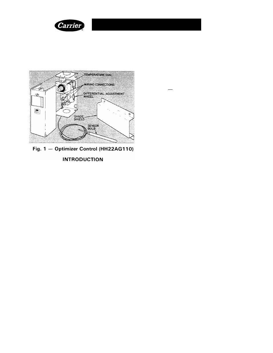
Accessory Optimizer Control
1176
400
55
189
X
12,000 Btuh = 35,280 Btuh
X 3.5 kW = 10.2 kW
Usage
— Install the Optimizer Control (Fig.
1)
with
Model 38CQ, HQ or RQ split system heat pump
that has been added to standard oil or gas furnace.
This Optimizer system provides cooling as required
and heating season operation that maximizes system
usage and benefits.
Optimizer usage is also beneficial in some heat
pump/electric furnace systems such as those with
Model 40ES. These Optimizer systems operate the
same as gas or oil furnace/heat pump systems.
CAUTION: If
saowfaB is over 20 in.
(508 mm), the minimum setpoint of the Opti
mizer Control is 35 F (L6 C),
OPTIMIZER SYSTEM
INSTALLATION REQUIREMENTS
^Indoor Airflow Capacity
of furnace fan and duct
system, as is, or with modification, must be approxi
mately 400 to 500 cfm per 12,000 Btuh (189 to 236 1/ s
per 3.5 kW) of heat pump cooling capacity (equiv
alent to 33 to 42 cfm per 1,000 Btuh [15.6 to 19.8 1/s
per .3 kW]). Determine existing system cfm capa
bility (without indoor coil installed) by standard
temperature rise or pressure drop methods. Calcu
late permissible cooling capacity.
Example:
System cfm capability = 1176 cfm (555 1/s)
Maximum heat pump cooling capacity permis
sible at 1176 cfm (555 1/s) with minimum require
ment of 400 cfm (189 1/s)/12,000 Btuh (3.5 kW):
With indoor coil installed, a larger furnace motor
or blower assembly may be required. After installing
coil, recheck cfm, and modify blower assembly or
duct system as required.
RECOMMENDED INDOOR COIL LOCATION
is on supply air side of gas or oil furnace, supply or
return air side of Electric Furnace (40ES). See
Fig. 2 and Coi/ Installation Instructions.
SYSTEM
INDOOR
THERMOSTAT
—
Use
thermostat-subbase
package
38CQ900-111
for
manual cooling/heating changeover; 38CQ900-081
for automatic cooling/heating changeover. Re
quired thermostat has manually operated emer
gency heat switch which locks out heat pump and
activates furnace.
SYSTEM TRANSFORMER (24-v) CAPACITY
required for most Optimizer systems is 60 va.
Replace gas or electric furnace transformer as re
quired with 60-va transformer. Carrier Part No.
HT01AW230.
If oil furnace has a 40-va (or less) transformer, and
accessory humidifier or air cleaner is wired in system,
add another transformer to system to acquire 60-va
total transformer capacity. Connect additional
transformer in parallel and in phase with existing
transformer as follows:
1. Connect 115-volt primary leads on 20-va trans
former to same points as primary leads on exist
ing transformer.
2. Attach one 24-volt secondary lead from 20-va
transformer to furnace terminal C or common
side of existing transformer.
3. Apply 115-volt power. Measure voltage between
unconnected 24-v lead, on 20-va transformer,
and terminal R on furnace. If voltage is zero,
connect 24-v lead to terminal R. (Transformers
are in phase.) If 50 volts (approximately) is
measured, reverse 115-v primary lead connection
on one transformer. Recheck voltage — if zero,
connect 24-v lead to terminal R.
FURNACE FAN RELAY is required. Add to fur
nace when not so equipped. Furnaces shown in
Control Circuit Connections, Fig. 3, have fan relay.
Carrier Corporation 1980
Form 38CQ-17SIM